7-10
A+ SERVER 4042G-6RF/TRF User's Manual
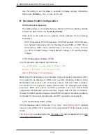
Use this setting to set the delay in seconds to display memory information.
Options are
No Delay
, 1 sec, 2 secs and 4 secs.
Hardware Health Configuration
CPU Overheat Temperature
This setting allows you to specify the type of alarm for CPU overheating. Options
include The Early Alarm and
The Default Alarm
.
Other items in the submenu are systems monitor displays for the following
information:
CPU1 Temperature, CPU2 Temperature, CPU3 Temperature, CPU4 Tempera-
ture, System Temperature, Fan 1-9 Reading, Chipset FAN1-2, CPU1 VCore,
CPU2 VCore, CPU3 VCore, CPU4 VCore, 3.3V Vcc (V), + 5Vin, +12V Vcc
(V), CPU1~4 DIMM Voltage, Chipset SR56x0 Voltage, 3.3V standby, Battery
Voltage
CPU Temperature Display (CTD)
CPU Temperature descriptions are defined as:
Low
[Tctl Value = Lowest Value, Tctl Value = -45]
Medium
[Tctl Value = -46, Tctl Value = 60]
High
[Tctl Value = -61 and Above]
Note:
Only CPU temperature (Low, Medium, High) and system temperature (RT1)
are required to be displayed in BIOS and in-system monitoring software. Other
Motherboard components such as memory, chipset, SAS and 10Gb controllers,
and others are not requried to display temperatures. For debugging and testing
purposes, BIOS and system monitoring software can show motherboard
components’ temperatures (such as memory, chipset, SAS and 10Gb controllers).
However for SMCI standard release version BIOS and system monitoring software,
motherboard components’ temperatures are NOT required to be displayed.
CPU Overheating Alarm (COA)
CPU Overheating Alarm (COA) has “
Early Alarm
” and “
Default Alarm
” (default)
options in the BIOS, and is required to be implemented in all fan speed control
modes.
The
Early Alarm
is enabled when the Tctl value = 65, and is disabled when the Tctl
value drops from 65 to 62.
Содержание A+ SERVER 4042G-6RF
Страница 1: ... SUPER A SERVER 4042G 6RF TRF USER S MANUAL Revision 1 0d ...
Страница 5: ...v Preface Notes ...
Страница 10: ...Notes x A SERVER 4042G 6RF TRF User s Manual ...
Страница 25: ...Chapter 2 Server Installation 2 9 Figure 2 5 Accessing the Inside of the System ...
Страница 30: ...3 4 4042G 6RF TRF User s Manual Notes ...
Страница 50: ...4 20 A SERVER 8027R TRF 7RFT User s Manual Notes ...
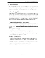
Страница 92: ...6 10 A SERVER 4042G 6RF TRF User s Manual Figure 6 7 Removing a Power Supply Module ...
Страница 110: ...A 2 A SERVER 4042G 6RF TRF User s Manual Notes ...


