background image


 X9SRA Motherboard Series User's Manual

B-4

Note:


Do not interrupt

 this process until BIOS flashing is completed.

9. 

After seeing the message that BIOS update is completed, unplug 

the AC power cable to clear CMOS, and then plug in the AC power cable 

to power on the system.

10. Press <Del> continuously to enter the BIOS Setup utility. 

11. Press <F3> to load default settings. 

12. After loading default settings, press <F4> to save the settings and exit the 

BIOS Setup utility.

Содержание 5037A-I

Страница 1: ...SuperWorkstation 5037A I SUPER USER S MANUAL 1 0...

Страница 2: ...any such disputes Super Micro s total liability for all claims will not exceed the price paid for the hardware product FCC Statement This equipment has been tested and found to comply with the limits...

Страница 3: ...732D4 903B chassis Chapter 2 Server Installation This chapter describes the steps necessary to set up the SuperWorkstation 5037A I and to check out the server configuration prior to powering up the sy...

Страница 4: ...apter 6 Advanced Chassis Setup Refer to Chapter 6 for detailed information on the SC732D4 903B chassis You should follow the procedures given in this chapter when installing removing or reconfiguring...

Страница 5: ...v Preface Notes...

Страница 6: ...3 Contacting Supermicro 1 5 Chapter 2 Installation 2 1 Overview 2 1 2 2 Unpacking the System 2 1 2 3 Preparing for Setup 2 1 Choosing a Setup Location 2 2 Server Cautions 2 2 Chapter 3 System Interfa...

Страница 7: ...and Removing DIMMs 5 10 5 7 Adding PCI Add On Cards 5 12 5 8 Motherboard Details 5 13 5 9 Connector Definitions 5 15 5 10 Jumper Settings 5 22 5 11 Onboard Indicators 5 25 5 12 SATA Ports 5 26 5 13 I...

Страница 8: ...1 Starting BIOS Setup Utility 7 1 How To Change the Configuration Data 7 1 How to Start the Setup Utility 7 2 7 2 Main Setup 7 2 7 3 Advanced Setup Configurations 7 4 7 4 Event Logs 7 20 7 5 Security...

Страница 9: ...been included with the SuperWorkstation 5037A I as listed below One 1 Rackmount kit MCP 290 00053 0N One 12 cm exhaust fan FAN 0124L4 SATA Accessories Four 3 5 SATA HDD bays in a 90 rotating hard driv...

Страница 10: ...s integrated into the chipset to provide a Serial ATA subsystem The 5037A I X9SRA supports two SATA 3 0 and eight SATA 2 0 ports PCI Expansion Slots The X9SRA has features the following PCI expansion...

Страница 11: ...ty overheat conditions and power supply failure A main power button and a system reset button are also included Note The power supply fail LED indicates the power supply fan has failed Cooling System...

Страница 12: ...AN1 82579 PCI E X1 G2 PCI E X1 G2 6 7 LAN2 82574 PCI E X1 G2 8 RJ45 RJ45 USB 3 0 14 15 1 2 3 4 6 7 COM2 Header SLOT 4 USB 2 0 6 0 Gb S Sandybridge EP PCH PATSBURG SSB D PCI E X16 G3 BIOS SIO NCT6776F...

Страница 13: ...e Address Super Micro Computer B V Het Sterrenbeeld 28 5215 ML s Hertogenbosch The Netherlands Tel 31 0 73 6400390 Fax 31 0 73 6416525 Email sales supermicro nl General Information support supermicro...

Страница 14: ...SuperWorkstation 5037A I User s Manual 1 6 Notes...

Страница 15: ...box the system was shipped in and note if it was damaged in any way If the system itself shows damage you should file a damage claim with the carrier who delivered it Decide on a suitable location for...

Страница 16: ...isual Display Units Server Cautions Review the electrical and general safety warnings in Chapter 4 Use a regulating uninterruptible power supply UPS to protect the server from power surges voltage spi...

Страница 17: ...of the system and the activity and health of specific components 3 2 Control Panel Buttons There are two push buttons located on the front of the chassis a power on off button and a reset button Powe...

Страница 18: ...by cables obstructing the airflow in the system or the ambient room temperature being too warm Correcting an Overheat Fan Fail Condition 1 Check the routing of the cables and move any cables that rest...

Страница 19: ...rst power down the sys tem with the operating system The unit has more than one power supply cord Disconnect both power supply cords before servicing to avoid electrical shock When working around expo...

Страница 20: ...d into a cooling fan Remove any jewelry or metal objects from your body which are excellent metal conductors that can create short circuits and harm you if they come into contact with printed circuit...

Страница 21: ...use Touch a grounded metal object before removing the board from the antistatic bag Do not let components or PCBs come into contact with your clothing which may retain a charge even if you are wearing...

Страница 22: ...ur if this practice is not strictly followed Figure 4 1 Installing the Onboard Battery Please handle used batteries carefully Do not damage the battery in any way a damaged battery may release hazardo...

Страница 23: ...nt to handle them very carefully see previous chapter To prevent the motherboard from bending keep one hand under the center of the board to support it when handling The following measures are general...

Страница 24: ...lip of the top cover of the chassis then pull the cover off 2 Make sure that the I O ports on the motherboard align properly with their respective holes in the I O shield at the back of the chassis 3...

Страница 25: ...locations SATA drive data cables I SATA0 I SATA5 Control panel cable JF1 SGPIO cable T SGPIO1 T SGPIO2 Caution Make sure that the cables do not come into contact with the fans Connecting Power Cables...

Страница 26: ...r Button Ground X Power On LED HDD LED NIC1 LED NIC2 LED OH Fan Fail LED Power Fail LED Ground Ground 2 1 20 19 1 1 1 10 1 11 1 12 1 13 1 14 1 15 1 18 1 16 1 19 1 17 1 2 1 3 1 4 1 5 1 6 1 7 1 8 1 9 Mo...

Страница 27: ...ink only Make sure to install the motherboard into the chassis before you install the CPU heatsinks When receiving a motherboard without a processor pre installed make sure that the plastic CPU socket...

Страница 28: ...ket WARNING OPEN1st WARNING Socket Keys CPU Keys Gently push down to pop the load plate open 5 Use your thumb and index finger to hold the CPU by its edges Align the CPU keys which are semi circle cut...

Страница 29: ...plate again and double check that the CPU is aligned properly OPEN1st OPEN1st Lever Lock Push down and lock the lever labeled Open 1st Push down and lock the level labeled Close 1st Gently close the...

Страница 30: ...he heatsink or the CPU die the required amount has already been applied 2 Place the heatsink on top of the CPU so that the four mounting holes are aligned with those on the motherboard and the heatsin...

Страница 31: ...cies safety_information cfm 1 Remove the power cord from the system before removing the heatsink 2 Unscrew the heatsink screws from the motherboard in the sequence as shown in the illustration below 3...

Страница 32: ...the desired number of DIMMs into the memory slots starting with P1 DIMM1A For best perfor mance please use the memory modules of the same type and speed in the same bank See the DIMM Installation Char...

Страница 33: ...ded Population Balanced DIMM1A DIMM2A DIMM3A DIMM4A DIMM1B DIMM2B DIMM3B DIMM4B Total System Memory 2GB 2GB 4GB 2GB 2GB 2GB 2GB 8GB 2GB 2GB 2GB 2GB 2GB 2GB 12GB 2GB 2GB 2GB 2GB 2GB 2GB 2GB 2GB 16GB 4G...

Страница 34: ...removing the PCI slot shield for the slot you wish to populate 2 Fully seat the card into the card slot pushing down with your thumbs evenly on both sides of the card 3 Finish by using a screw to secu...

Страница 35: ...very 2 3 Normal SLOT6 PCI E 3 0 X16 SLOT4 PCI E 3 0 X16 SLOT2 PCI E 3 0 X4 IN X8 SLOT1 PCI E 2 0 X4 IN X8 1 2 ENABLE 2 3 DISABLE JPT1 USB12 13 USB10 11 COM1 1 2 ENABLE JPAC1 AUDIO 2 3 DISABLE AUDIO FP...

Страница 36: ...ec SAS 2 0 3Gb sec X9SRA only Not supported 3 SGPIO1 3 SGPIO2 Serial General Purpose I O Headers for SAS I SATA0 I SATA1 Serial ATA ports SATA 3 0 6Gb s I SATA2 5 Serial ATA ports SATA 2 0 3Gb s JWF1...

Страница 37: ...JPW1 Pin Definition Pin Definition 13 3 3V 1 3 3V 14 12V 2 3 3V 15 COM 3 COM 16 PS_ON 4 5V 17 COM 5 COM 18 COM 6 5V 19 COM 7 COM 20 Res NC 8 PWR_OK 21 5V 9 5VSB 22 5V 10 12V 23 5V 11 12V 24 COM 12 3 3...

Страница 38: ...2 USB_PN1 6 USB_PN0 3 USB_PP1 7 USB_PP0 4 Ground 8 Ground Front Panel USB 2 0 Header Pin Definitions Pin Definition Pin Definition 1 5V 2 5V 3 USB_PN2 4 USB_PN3 5 USB_PP2 6 USB_PP3 7 Ground 8 Ground 9...

Страница 39: ...ctivities Refer to the table on the right for pin definitions LAN1 LAN2 LED Pin Definitions JF1 Pin Definition 9 11 LED VCC 10 12 Ground HDD LED The HDD LED connection is located on pins 13 and 14 of...

Страница 40: ...N Use for 1 4 System CPU A I O Cards Speaker JD1 On the JD1 header Pins 3 4 are used for the internal speaker Close Pins 3 4 with a jumper or cap to use the onboard speaker If you wish to use an exter...

Страница 41: ...JPI2 C monitors the status of the power supply fan and system temperature See the table on the right for pin definitions PWR Supply I2 C Pin Definitions Pin Definition 1 Clock 2 Data 3 PWR Fail 4 Gro...

Страница 42: ...d state DOM storage device connected to one of the SATA ports See the table on the right for pin definitions DOM PWR Pin Definitions Pin Definition 1 5V 2 Ground 3 Ground Serial Ports Two COM headers...

Страница 43: ...Ground SPDIF_Out Pin Definitions Pin Definition 1 S PDIF_Out 2 Ground A COM1 B COM2 C Audio Header Front Accessible Audio Header A 10 pin Audio header is located on the motherboard at AUDIO FP This he...

Страница 44: ...r CMOS JBT1 JBT1 is used to clear CMOS Instead of pins this jumper consists of contact pads to prevent accidental clearing of CMOS To clear CMOS use a metal object such as a small screwdriver to touch...

Страница 45: ...r Settings Jumper Setting Definition Pins 1 2 Reset default Pins 2 3 NMI Open Disabled TPM Support Enable JPT1 JPT1 allows the user to enable TPM Trust ed Platform Module support to improve data integ...

Страница 46: ...ition 1 2 Enabled default 2 3 Disabled ME Recovery JPME1 ME Recovery JPME1 is used to enable or disable the ME Recovery feature of the motherboard Install the jumper on pins 1 2 for normal operation I...

Страница 47: ...the tables at right for more information LAN Link LEDs Green Amber Off LED Color Definition Off No Connection or 10 Mbps Green 100 Mbps Amber 1 Gbps Activity LED Link LED LAN Onboard Power LED DP2 An...

Страница 48: ...SATA SAS Ports Pin Definitions Pin Signal 1 Ground 2 SATA_TXP 3 SATA_TXN 4 Ground 5 SATA_RXN 6 SATA_RXP 7 Ground 1 SAS 0 2 SAS 1 3 SAS 2 4 SAS 3 SATA Ports There are four 4 SATA 2 0 ports two 2 SATA...

Страница 49: ...ed with your motherboard Driver Tool Installation Display Screen Note Click the icons showing a hand writing on paper to view the readme files for each item Click the computer icons to the right of th...

Страница 50: ...onment and operations of your system SuperDoctor III displays crucial system information such as CPU temperature system voltages and fan status See the Figure below for a display of the SuperDoctor II...

Страница 51: ...Interface Display Screen Remote Control Note The SuperDoctor III program and User s Manual can be downloaded from the Supermicro Web site at http www supermicro com products accessories software Supe...

Страница 52: ...pose of used batteries according to the manufacturer s instructions Figure 5 5 Installing the Onboard Battery LITHIUM BATTERY BATTERY HOLDER BATTERY HOLDER LITHIUM BATTERY OR Please handle used batter...

Страница 53: ...pment from static discharge Cautions Use a grounded wrist strap designed to prevent static discharge Touch a grounded metal object before removing any board from its antistatic bag Handle a board by i...

Страница 54: ...emoving the Power Cord 1 Use the operating system to Power down the system following the on screen prompts 2 After the system has completely shut down carefully grasp the head of the power cord and ge...

Страница 55: ...Chapter 6 Advanced Chassis Setup 6 3 Eight SATA Drive Bays Inside chassis interior Figure 6 1 Chassis Front View Main Power Audio Microphone USB Ports 2x USB 3 0 and 2x USB 2 0...

Страница 56: ...n the front control panel PCB printed circuit board Pull all excess cabling over to the control panel side of the chassis The LEDs on the control panel inform you of system status see Figure 6 2 for d...

Страница 57: ...left cover from the chassis 5 Remove the three screws securing the right side cover to the chassis 6 Slide the right cover toward the rear of the chassis 7 Lift the right cover from the chassis Cautio...

Страница 58: ...ns the exhaust fan and the power supply fans run continuously The chassis fans are hot pluggable and can be replaced without powering down the system Replacing Chassis Cooling Fans Removing a Fan 1 Fi...

Страница 59: ...Chapter 6 Advanced Chassis Setup 6 7 Figure 6 4 Removing a Chassis Fan...

Страница 60: ...he side panel of the chassis to access these drives as described in Chapter Caution Regardless of how many SATA drives are installed all drive carriers must remain in the drive bays to promote proper...

Страница 61: ...he sides of the hard drive carrier outward 7 Remove the hard drive from the hard drive carrier Figure 6 6 Removing the Hard Drive Carrier from the Hard Drive Cage 1 5 Release Tabs 1 4 Figure 6 7 Remov...

Страница 62: ...until it clicks into a locked position 10 If desired each hard drive carrier may be secured to the exterior of the hard drive cage using one optional screw 11 Rotate the hard drive cage 90 degrees in...

Страница 63: ...732D4 900B chassis must be powered down before hard drives can be removed from the hard drive carriers Removing and Installing 2 5 Hard Drives 1 Disconnect the chassis from any power source 2 Loosen t...

Страница 64: ...the hard drive carrier into the hard drive cage sliding it towards the back of the the hard drive cage until it clicks into a locked position 9 Slide the 2 5 hard drive cage back into the chassis and...

Страница 65: ...e 2 Disconnect the motherboard cables 3 Remove the screws securing the power supply to the chassis which are located on the rear of the chassis Set these screws aside for later use 4 Gently lift the p...

Страница 66: ...6 14 SuperWorkstation 5037A I User s Manual Notes...

Страница 67: ...displays all the options that can be configured Grayed out options cannot be configured Options in blue can be configured by the user The right frame displays the key legend Above the key legend is an...

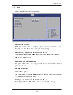
Страница 68: ...mages arising from a BIOS update If you have to update the BIOS do not shut down or reset the system while the BIOS is updating This is to avoid possible boot failure 7 2 Main Setup When you first ent...

Страница 69: ...e or Sys tem Date using the arrow keys Enter new values through the keyboard Press the Tab key or the arrow keys to move between fields The date must be entered in Day MM DD YY format The time is ente...

Страница 70: ...it For F1 If Error This forces the system to wait until the F1 key is pressed if an error occurs The options are Disabled and Enabled Interrupt 19 Capture Interrupt 19 is the software interrupt that h...

Страница 71: ...e to set the power state after a power outage Select Stay Off for the system power to remain off after a power loss Select Power On for the system power to be turned on after a power loss Select Last...

Страница 72: ...nabled to use the processor s Advanced Encryption Standard AES feature The options are Enabled and Disabled Hardware Prefetcher Available when supported by the CPU If set to Enabled the hardware pre f...

Страница 73: ...nformation The options are Disabled and Enabled Turbo Mode This feature allows processor cores to run faster than marked frequency in specific conditions The options are Disabled and Enabled C1E Suppo...

Страница 74: ...with greater reliabil ity security and availability in networking and data sharing The settings are Enabled and Disabled Intel I OAT The Intel I OAT I O Acceleration Technology significantly reduces...

Страница 75: ...gger fail over The spare memory is put online and used as active memory in place of the failed memory DRAM RAPL Mode RAPL which stands for Running Average Power Limit is a feature that provides mechan...

Страница 76: ...d the read data from memory turns out to be a correctable error the error is corrected and sent to the requestor the original source Memory is updated as well Select Enabled to use Demand Scrubbing fo...

Страница 77: ...ed by the EHCI driver The settings are Enabled and Disabled GbE Controller Select Enabled to activate the onboard gigabit Ethernet controller The settings are Enabled and Disabled Wake on LAN from S5...

Страница 78: ...Enhanced AHCI Mode The following items are displayed when AHCI Mode is selected Aggressive Link Power Management This feature Enables or Disables Agressive Link Power Management support for Cougar Poi...

Страница 79: ...PCI Latency Timer This feature sets the latency Timer of each PCI device installed on a PCI bus Se lect 64 to set the PCI latency to 64 PCI clock cycles The options are 32 PCI Bus Clocks 64 PCI Bus C...

Страница 80: ...LAN Option ROM Select This feature selects whether to load the iSCSI or PXE onboard LAN option ROM The options are iSCSI and PXE Load Onboard LAN1 Option ROM Load Onboard LAN2 Option ROM This feature...

Страница 81: ...11 12 IO 2E8h IRQ 3 4 5 6 7 9 10 11 12 The options for Serial Port 2 are Auto IO 2F8h IRQ 3 IO 3F8h IRQ 3 4 5 6 7 9 10 11 12 IO 2F8h IRQ 3 4 5 6 7 9 10 11 12 IO 3E8h IRQ 3 4 5 6 7 9 10 11 12 IO 2E8h I...

Страница 82: ...Band Manage ment Windows Emergency Management Services EMS ports The options are Enabled and Disabled Console Redirection Settings Configure the following options for the Console Redirection Settings...

Страница 83: ...ed as the normal operating state The CPU temperature is well below the CPU Temperature Tolerance The mother board fans and CPU will run normally as configured in the BIOS Fan Speed Control User interv...

Страница 84: ...e in these options High Precision Event Timer Select Enabled to activate the High Performance Event Timer HPET that produces periodic interrupts at a much higher frequency than a Real time Clock RTC d...

Страница 85: ...tus Intel TXT LT SX Configuration Intel TXT Initialization Intel TXT Trusted Execution Technology helps protect against software based at tacks and ensures protection confidentiality and integrity of...

Страница 86: ...s Smbios Event Log Change this item to enable or disable all features of the Smbios Event Log ging during boot The options are Enabled and Disabled Runtime Error Logging Support Change this item to en...

Страница 87: ...ed The options are Disabled and Enabled MECI The Multiple Event Count Increment MECI counter counts the number of occurences a duplicate event must happen before the MECI counter is incre mented This...

Страница 88: ...hange an existing User password BIOS SETUP UTILTY Select Screen Select Item Enter Select Change Opt F1 General Help F2 Previous Values F3 Optimized Defaults F4 Save Exit ESC Exit Version x xx xxxx Cop...

Страница 89: ...dd New Boot Option Delete Boot Option This feature allows the user to delete a previously defined boot device from which the systems boots from during startup Boot Option 1 Boot option 2 Boot Option 3...

Страница 90: ...this option to save any changes made This will not reset reboot the system Discard Changes Select this option and press Enter to discard all the changes and return to the AMI BIOS Utility Program Rest...

Страница 91: ...up for future use Restore User Defaults To set this feature select Restore User Defaults from the Exit menu and press En ter Use this feature to retrieve user defined settings that were saved previous...

Страница 92: ...7 26 SuperWorkstation 5037A I User s Manual Notes...

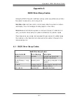
Страница 93: ...rror oc curs you should consult with your system manufacturer for possible repairs These fatal errors are usually communicated through a series of audible beeps The numbers on the fatal error list cor...

Страница 94: ...A 2 SuperWorkstation 5037A I User s Manual Notes...

Страница 95: ...ntrol to a computer system at bootup How to Recover the UEFI BIOS Image the Main BIOS Block An AMIBIOS flash chip consists of a boot sector block and a main BIOS code block a main BIOS image The boot...

Страница 96: ...Rom into your USB drive and power on the system 3 While powering on the system keep pressing Ctrl and Home simultane ously on your PS2 or USB keyboard until your hear two short beeps This may take fro...

Страница 97: ...tem Flash update progress 47 6 After the process of BIOS Recovery is complete press any key to reboot the system 7 Using a different system extract the BIOS package into a bootable USB flash drive 8 W...

Страница 98: ...message that BIOS update is completed unplug the AC power cable to clear CMOS and then plug in the AC power cable to power on the system 10 Press Del continuously to enter the BIOS Setup utility 11 P...

Страница 99: ...ffered ECC RDIMM memory or 64GB of DDR3 Unbuffered non ECC UDIMM memory up to 1600MHz Note See the memory section in Chapter 5 for details SATA Controller Intel on chip controller for two port SATA 3...

Страница 100: ...ng Environment Operating Temperature 10 to 35 C 50 to 95 F Non operating Temperature 40 to 60 C 40 to 148 F Operating Relative Humidity 8 to 90 non condensing Non operating Relative Humidity 5 to 95 n...

Страница 101: ...C 3 Appendix D System Specifications Notes...

Страница 102: ...erform be reasonably expected to result in significant injury or loss of life or catastrophic property damage Accordingly Supermicro dis claims any and all liability and should buyer use or sell such...

Отзывы: