


47
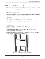
Chapter 3: Maintenance and Component Installation
Attaching the Processor Package Assembly to the Heatsink to
Form the Processor Heatsink Module (PHM)
After you have made a processor package assembly by following the instructions on the
previous page, please follow the steps below to mount the processor package assembly onto
the heatsink to create the Processor Heatsink Module (PHM).
1. Locate "1" on the heatsink label and the triangular corner next to it on the heatsink.
With your index finger pressing against the screw at this triangular corner, carefully hold
and turn the heatsink upside down with the thermal-grease side facing up. Remove the
protective thermal film if present, and apply the proper amount of the thermal grease
as needed. (Skip this step if you have a new heatsink because the necessary thermal
grease is pre-applied in the factory.)
2. Holding the processor package assembly at the center edge, turn it upside down. With
the thermal-grease side facing up, locate the hollow triangle located at the corner of the
processor carrier assembly ("a" in the graphic). Note a larger hole and plastic mounting
clicks located next to the hollow triangle. Also locate another set of mounting clicks and
a larger hole at the diagonal corner of the same (reverse) side of the processor carrier
assembly ("b" in the graphic).
3. With the back of heatsink and the reverse
side of the processor package assembly
facing up, align the triangular corner on
the heatsink ("A" in the graphic) against
the mounting clips next to the hollow
triangle ("a") on the processor package
assembly.
4. Also align the triangular corner ("B") at
the diagonal side of the heatsink with
the corresponding clips on the processor
package assembly ("b").
5. Once the mounting clips on the processor
package assembly are properly aligned
with the corresponding holes on the back
of heatsink, securely attach the heatsink
to the processor package assembly by
snapping the mounting clips at the proper
places on the heatsink to create the
processor heatsink module (PHM).
Heatsink
(Upside Down)
Non-Fabric CPU and Processor Clip
(Upside Down)
C
D
d
c
a
b
A
B
On Locations of (C, D),
the notches
snap onto the heat sink’s
mounting holes
On Locations (A, B), the notches
snap onto the heatsink’s sides
A
B
D
C
Make sure Mounting
Notches snap into place
Triangle on the CPU
Triangle on the
Processor Clip
Содержание SuperServer 7089P-TR4T
Страница 1: ...USER S MANUAL Revision 1 0 SuperServer 7089P TR4T ...
Страница 56: ...SuperServer 7089P TR4T User s Manual 56 Figure 3 4 Removing a PCI E Card from a PCIE Module 5 6 ...
Страница 59: ...59 Chapter 3 Maintenance and Component Installation Figure 3 6 Installing a PCI E Card in a CPU Module ...
Страница 60: ...SuperServer 7089P TR4T User s Manual 60 Figure 3 7 Installing a PCI E Card in a CPU Module cont ...
Страница 62: ...SuperServer 7089P TR4T User s Manual 62 Figure 3 9 Installing a PCI E Card in a Storage Module ...
Страница 64: ...SuperServer 7089P TR4T User s Manual 64 Figure 3 11 Installing the Battery 3 2 ...
Страница 69: ...69 Chapter 3 Maintenance and Component Installation Figure 3 16 Installing Removing 2 5 HDDs with bracket ...