Sun Microsystems UltraSPARC III Cu Module Скачать руководство пользователя страница 24

16

Sun Blade 1000 and Sun Blade 2000 UltraSPARC III Cu Module Installation Guide • June 2004

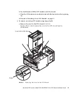
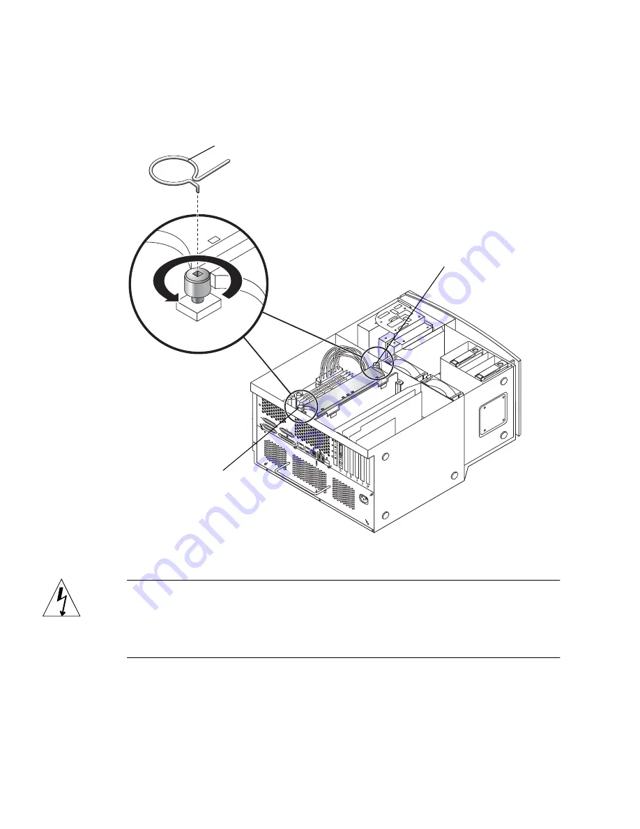
b. Alternately rotate the left and right captive screws one turn counterclockwise

until the screws are free of the threaded inserts

(

FIGURE 10

)

.

FIGURE 10

Using Torque Tool B to Remove the CPU Module

Caution –

As you remove the module from the shroud, handle it only by its

captive screws. Do not touch the connectors on the bottom edge of the module or the
electrical components on the module. The connectors and the components for the
module are easily bent or damaged by improper handling and by electrostatic
discharge (

FIGURE 11

).

c. Use both hands to lift the CPU module out of the shroud.

d. Place the CPU module on an antistatic mat with the heat sink on the top facing

up.

Right captive screw

Torque tool B

Left captive
screw

Содержание UltraSPARC III Cu Module

Страница 1: ...rcle Santa Clara CA 95054 U S A 650 960 1300 Submit comments about this document at http www sun com hwdocs feedback Sun Blade 1000 and Sun Blade 2000 UltraSPARC III Cu Module Installation Guide Part...

Страница 2: ...s Tous droits r serv s Ce produit ou document est distribu avec des licences qui en restreignent l utilisation la copie la distribution et la d compilation Aucune partie de ce produit ou document ne p...

Страница 3: ...onfiguration Rules 3 Identifying Cu CPU Modules 3 Identifying a CPU Module 3 OpenBoot PROM and Software Requirements for UltraSPARC III Cu CPU Modules 5 Installing the UltraSPARC III Cu CPU Module 5 V...

Страница 4: ...iv Sun Blade 1000 and Sun Blade 2000 UltraSPARCTM III Cu Module Installation Guide June 2004 Installing a New CPU Module 17 Finishing the Installation 25 Where to Find More Information 26...

Страница 5: ...not approved by Sun Microsystems Inc may void the authority granted to the user by the FCC to operate this equipment FCC Class B Notice This device complies with Part 15 of the FCC Rules Operation is...

Страница 6: ...sse A This Class A digital apparatus complies with Canadian ICES 003 Cet appareil num rique de la classe A est conforme la norme NMB 003 du Canada ICES 003 Class B Notice Avis NMB 003 Classe B This Cl...

Страница 7: ...vii BSMI Class A Notice The following statement is applicable to products shipped to Taiwan and marked as Class A on the product compliance label...

Страница 8: ...viii Sun Blade 1000 and Sun Blade 2000 UltraSPARCTM III Cu Module Installation Guide June 2004...

Страница 9: ...PU Modules on page 3 OpenBoot PROM and Software Requirements for UltraSPARC III Cu CPU Modules on page 5 Installing the UltraSPARC III Cu CPU Module on page 5 Where to Find More Information on page 26...

Страница 10: ...s you may need Rules for Installing Cu CPU Modules You should verify which CPU modules are installed in your workstation before you purchase or install new CPU modules Note UltraSPARC III Cu CPU modul...

Страница 11: ...figuration Rules The Sun Blade 2000 workstation only operates with UltraSPARC III Cu CPU modules If two Cu CPUs are installed they must be identical speeds For example two 1 200 GHz Cu C modules or tw...

Страница 12: ...ng the label on the UltraSPARC III Cu module usr platform SUNW Sun Blade 1000 sbin prtdiag CPUs E CPU CPU Temperature CPU Freq Size Implementation Mask Die Amb Location 0 1056 MHz 8MB SUNW UltraSPARC...

Страница 13: ...workstation Installing the UltraSPARC III Cu CPU Module Before installing an UltraSPARC III Cu CPU module verify the hardware and software compatibility as described in the next section Verifying Soft...

Страница 14: ...You must install the correct Solaris operating environment and OpenBoot PROM versions before installing the CPU or the system will not boot Preparing for Installation This section describes how to Pow...

Страница 15: ...he ok Prompt OpenBoot PROM Interface 1 Press and hold the front panel power switch for four seconds FIGURE 2 to power off the workstation This action forces an immediate power off of the workstation A...

Страница 16: ...off The workstation fans are not spinning 2 Turn off power to the monitor and other external peripherals 3 Disconnect the cables for any peripheral equipment 4 Remove the lock block if one is installe...

Страница 17: ...l activates the workstation power interlock circuit This safety mechanism prevents all DC voltages except 5 VDC standby power from reaching any internal components 1 Press down on the two depressions...

Страница 18: ...10 Sun Blade 1000 and Sun Blade 2000 UltraSPARC III Cu Module Installation Guide June 2004 FIGURE 4 Removing the Access Panel 1 2 3 4 Access panel Depression 2...

Страница 19: ...cord from the workstation and the wall receptacle This procedure equalizes all electrical potentials within the workstation 1 Place the workstation on its side on a work surface open side facing up F...

Страница 20: ...See FIGURE 6 The CPU modules are enclosed in a cooling shroud and secured to the shroud with captive screws that must be torqued to specific values Note Beginning in June 2004 CPU torque tools are not...

Страница 21: ...ecessary remove the filler panel FIGURE 7 Squeeze the two tabs on the filler panel to release it from the cover for the CPU shroud FIGURE 7 Removing the Filler Panel 4 Complete one of the following st...

Страница 22: ...odule 5 To remove an existing CPU module using torque tool A a Alternately rotate the left and right captive screws one turn counterclockwise until the screws are free of the threaded inserts FIGURE 8...

Страница 23: ...n antistatic mat with the heat sink on the top facing up d Proceed to Installing a New CPU Module on page 17 6 To remove an existing CPU module using torque tool B a Remove the cover for the CPU shrou...

Страница 24: ...ove the module from the shroud handle it only by its captive screws Do not touch the connectors on the bottom edge of the module or the electrical components on the module The connectors and the compo...

Страница 25: ...lacing them on any surface 2 When you remove the CPU module from its packing carton use both hands to support the module along its sides Do not grip the module by the heat sink 3 As you remove the mod...

Страница 26: ...ver from the CPU module connector FIGURE 11 FIGURE 11 Removing the Plastic Cover From the CPU Module Connectors 2 Lower the CPU module into the CPU shroud until the captive screws are aligned with the...

Страница 27: ...ighten both captive screws by hand until the screws contact the threaded inserts of the CPU shroud Once the CPU module is seated surface contact between the captive screws and the threaded inserts of...

Страница 28: ...0 and Sun Blade 2000 torque tools are designed specifically for your workstation 6 Use torque tool B to rotate the right captive screw one turn clockwise FIGURE 13 FIGURE 13 Alternately Rotating Left...

Страница 29: ...ys rotate the left captive screw one turn clockwise and then rotate the right captive screw one turn clockwise This assures that a uniform and even torque is applied to the CPU module FIGURE 14 Adjust...

Страница 30: ...rque tool A to rotate the left captive screw one turn clockwise FIGURE 16 If the torque tool clicks stop Do not attempt to torque the captive screw anymore 11 Use torque tool A to rotate the right cap...

Страница 31: ...ft and Right Captive Screws One Turn Clockwise 12 Repeat steps 10 and 11 until torque tool A clicks FIGURE 17 Seating occurs when both captive screws are evenly torqued to 5 inch lbs 58 grams meter To...

Страница 32: ...location in the workstation 14 If necessary reinstall the filler panel for the shroud Caution To ensure proper workstation cooling any unused CPU slot must contain a filler panel for the shroud FIGUR...

Страница 33: ...ral seconds verify that the power indicator LED on the power switch is energized and listen to verify that the workstation fans are operating spinning 7 The workstation should automatically recognize...

Страница 34: ...ble from the following sources The manual is shipped with new workstations in HTML and PDF formats on the Sun Blade 1000 and Sun Blade 2000 Hardware Documentation CD 705 0073 The HTML version of the m...

Отзывы: