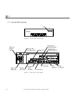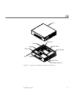
Power-On Self-Test (POST)
3-3
3
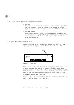
To return to the default setting:
To observe POST messages on serial port A, you must connect a terminal to
port A or set up a tip connection to another workstation. For information about
setting up tip connections, refer to the Solaris software reference manuals.
3.3 POST Progress and Error Reporting
While POST is running, observe the Caps Lock key on the system keyboard. It
should flash on and off to indicate that tests are running. Additional POST
progress indication is visible when a terminal or tip line is connected to serial
port A.
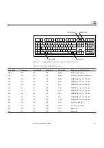
If an error occurs during POST, the Caps Lock key will stop flashing and an
error code will be displayed using the lights on the keyboard's Caps Lock,
Compose, Scroll Lock, and Num Lock keys.
Note –
The error code may only be visible for a few seconds, so it is important
to observe the keyboard lights closely while POST is running.
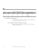
If an error code is present on the keyboard, compare the pattern to Table 3-1 for
the meaning of the failure. The failure code will indicate a part of the system
hardware that was tested by POST to be defective or missing.
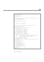
In most cases, POST will also attempt to send a failure message to the system
monitor. In this case, a message such as this will be displayed:
The system will not automatically boot if a POST error occurs. It will halt at the
ok
prompt to alert the user of the failure.
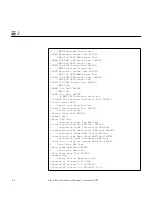
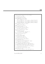
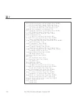
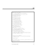
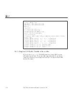
ok setenv diag-level max
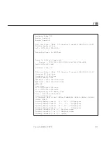
Power On Self Test Failed. Cause: SIMM U0701 or System Board
ok
Содержание Ultra 1 140
Страница 6: ......
Страница 8: ...Sun Ultra 1 Series Service Manual November 1995...
Страница 12: ...x Sun Ultra 1 Series Service Manual November 1995 Glossary Glossary 1 Index Index 1...
Страница 23: ...Part1 SystemInformation Product Description page 1 1...
Страница 24: ......
Страница 28: ...1 4 Sun Ultra 1 Series Service Manual November 1995 1...
Страница 30: ......
Страница 46: ...3 14 Sun Ultra 1 Series Service Manual November 1995 3...
Страница 62: ...4 16 Sun Ultra 1 Series Service Manual November 1995 4...
Страница 63: ...Part3 PreparingforService Safety and Tool Requirements page 5 1 Power On and Off page 6 1...
Страница 64: ......
Страница 68: ...5 4 Electron Service Manual November 1995 5...
Страница 72: ......
Страница 108: ...8 32 Sun Ultra 1 Series Service Manual November 1995 8...
Страница 121: ...Part5 SystemBoard System Board and Component Replacement page 10 1...
Страница 122: ......
Страница 147: ...Part6 IllustratedPartsBreakdown Replacement Parts page 11 1...
Страница 148: ......
Страница 152: ......
Страница 166: ...C 4 Sun Ultra 1 Series Service Manual November 1995 C...
Страница 170: ...Glossary 4 Sun Ultra 1 Series Service Manual November 1995...
Страница 174: ...Index 4 Sun Ultra 1 Series Service Manual November 1995...

