background image

C-1

Functional Description

C

C.1 System Features

The Sun Ultra 1 Series system conforms to the Sun4u system architecture. The
CPU board contains a single UltraSPARC

 microprocessor. The system can

have up to two 3.5-inch (88.9 mm) hard disk drives, an optional CD-ROM
drive or a tape drive, and an optional 3.5-inch (88.9 mm) diskette drive. It has
three SBus slots.

Random access memory (RAM) is implemented with dynamic single inline
memory modules (DSIMMs). Each system provides eight DSIMM slots, and
has a minimum of two DSIMMs installed.

System Features

page C-1

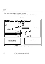
Sun Ultra 1 Series System Block Diagram

page C-2

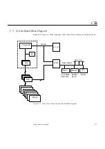
System Board Block Diagram

page C-3

Содержание Ultra 1 140

Страница 1: ...MARQUETTE A PARTOFTHE U N I T Y N E T W O R K service manual PN 408287 051 Revision A Sun Ultra 1 Series...

Страница 2: ...TE MARQUETTE MAC MARQUETTE UNITY NETWORK MARS MAX MEDITEL MEI MEI in the circle logo MEMOPORT MEMOPORT C MINISTORE MINNOWS Monarch 8000 MULTI LINK MULTISCRIPTOR MUSE MUSE CV Neo Trak NEUROSCRIPT Onlin...

Страница 3: ...ra 1Series ServiceManual Part No 802 3819 10 Revision A November 1995 The Network Is the Computer Sun Microsystems Computer Company 2550 Garcia Avenue Mountain View CA 94043 USA 415 960 1300 fax 415 9...

Страница 4: ...roduct service or company names mentioned herein are claimed as trademarks and trade names by their respective companies All SPARC trademarks are trademarks or registered trademarks of SPARC Internati...

Страница 5: ...Unis et dans certains d autres pays Toutes les marques SPARC utilis es sous license sont des marques d pos es ou enregistr es de SPARC International Inc aux Etats Unis et dans d autres pays Les produ...

Страница 6: ......

Страница 7: ...802 3819 05 August 1995 Chapter 3 and 4 are to be completed on the next revision Some of the illustrations need to be modified The comments for the artist are placed next to them The board fan is bein...

Страница 8: ...Sun Ultra 1 Series Service Manual November 1995...

Страница 9: ...2 Part 2 Troubleshooting 2 SunVTS Overview 2 1 3 Power On Self Test POST 3 1 3 1 How to Start POST 3 1 3 2 Max and Min Levels of POST 3 2 3 3 POST Progress and Error Reporting 3 3 3 4 Additional Keybo...

Страница 10: ...all test 4 13 4 8 System Board Test 4 14 Part 3 Preparing for Service 5 Safety and Tool Requirements 5 1 5 1 Safety Requirements 5 1 5 2 Symbols 5 1 5 3 Safety Precautions 5 2 5 4 Tools Required 5 3...

Страница 11: ...9 6 9 3 Diskette Drive 9 11 Part 5 System Board 10 System Board and Component Replacement 10 1 10 1 System Board 10 2 10 2 NVRAM TOD 10 10 10 3 SBus Card 10 12 10 4 DSIMM 10 18 10 5 System Board Fan...

Страница 12: ...x Sun Ultra 1 Series Service Manual November 1995 Glossary Glossary 1 Index Index 1...

Страница 13: ...Power Supply Connector J2601 4 4 Figure 4 2 Power Supply Connector J2603 4 5 Figure 6 1 Rear View of the System 6 2 Figure 7 1 Location of Lock Block 7 1 Figure 7 2 Removing the Cover 7 2 Figure 7 3 A...

Страница 14: ...8 15 Removing the SCSI Backplane 8 18 Figure 8 16 Replacing the SCSI Backplane 8 19 Figure 8 17 Removing the Drive Bracket 8 20 Figure 8 18 Removing the Peripheral Power Cable 8 21 Figure 8 19 Periph...

Страница 15: ...ctor on the System Board 10 4 Figure 10 3 Captive Screws on the Back Panel 10 4 Figure 10 4 Sliding the System Board Out of the Chassis 10 5 Figure 10 5 Removing SBus Filler Panels from the Back Panel...

Страница 16: ...Fan 10 23 Figure 10 21 Board Fan 10 24 Figure B 1 Keyboard Mouse Connector B 1 Figure B 2 Serial Ports A and B Connector B 2 Figure B 3 AUI Connector B 3 Figure B 4 TPE Connector B 4 Figure B 5 SCSI...

Страница 17: ...ory Address 4 6 Table 4 4 Internal Drives Identification 4 7 Table 4 5 Selected On Board Diagnostics Tests 4 12 Table 8 1 Peripheral Power Cable Connection 8 21 Table 10 1 Serial Port Jumper Settings...

Страница 18: ...Keyboard Mouse Pin Assignments B 1 Table B 2 Serial Ports Pin Assignments B 2 Table 11 2 AUI Connector Pinouts B 3 Table B 3 TPE Pin Assignments B 4 Table B 4 SCSI Pin Assignments B 5 Table B 5 Audio...

Страница 19: ...t manufacturers OEMs value added resellers VARs and other customers with self maintenance contracts Related Documentation The following documents provide additional information for servicing the Sun U...

Страница 20: ...Cc123 The names of commands files and directories on screen computer output Edit your login file Use ls a to list all files machine_name You have mail AaBbCc123 What you type contrasted with on screen...

Страница 21: ...ers to access this equipment must observe all safety precautions and ensure compliance with skill level requirements certification and all applicable local and national laws Procedures contained in th...

Страница 22: ...orders You can order documentation in the following ways Sun Welcomes Your Comments Please use the Reader Comment Card that accompanies this document We are interested in improving our documentation a...

Страница 23: ...Part1 SystemInformation Product Description page 1 1...

Страница 24: ......

Страница 25: ...workstation are CPU system Monitor Sun Type 5c keyboard Compact 1 mechanical mouse The following figures illustrate the CPU system Figure 1 1 shows the front view of the system Figure 1 2 shows the re...

Страница 26: ...tem Figure 1 2 Rear View of the System LED Power outlet Female socket Power inlet Male plug Parallel connector AUI connector Audio connectors Power on standby switch SBus slot 2 Serial port A RS 423 R...

Страница 27: ...Product Description 1 3 1 Figure 1 3 Top View of the System with the Cover Removed Cover DSIMMs Chassis Power supply System board Disk drive Diskette Drive CD ROM or tape drive Fan Speaker SBus card...

Страница 28: ...1 4 Sun Ultra 1 Series Service Manual November 1995 1...

Страница 29: ...Part2 Troubleshooting SunVTS Overview page 2 1 Power On Self Test POST page 3 1 Troubleshooting Procedures page 4 1...

Страница 30: ......

Страница 31: ...oordinates the running of individual tests and manages the messages sent by these tests SunVTS OPEN LOOK user interface vtsui This interface is designed to run on top of OpenWindows Through the numero...

Страница 32: ...on the SMCC Updates CD for the Solaris release you are running Sun VTS User s Guide 801 7271 This document describes the SunVTS environment including how to start and control the various user interfa...

Страница 33: ...ways Before powering up the system press and hold the Stop and D keys on the keyboard With these keys pressed turn the system on by pressing the keyboard power on key or press the power on switch at t...

Страница 34: ...ST are available in the system max maximum level and min minimum level The system runs the selected level of POST based on the setting of the NVRAM variable called diag level The default setting for d...

Страница 35: ...ng and an error code will be displayed using the lights on the keyboard s Caps Lock Compose Scroll Lock and Num Lock keys Note The error code may only be visible for a few seconds so it is important t...

Страница 36: ...appears on the monitor 3 5 System and Keyboard LEDs The power LED at the front of the chassis remains lit when the system is operating normally Figure 3 1 shows the location of the power LED Figure 3...

Страница 37: ...MM in slot U 0601 fail Off Off On Off 0010 DSIMM in slot U 0701 fail Off Off On On 0011 DSIMM in slot U 0602 fail Off On Off Off 0100 DSIMM in slot U 0702 fail Off On Off On 0101 DSIMM in slot U 0603...

Страница 38: ...A on the Sun Ultra 1 Series system 3 6 1 Diag level NVRAM Variable is Set to Max Following is an example of serial port A POST output when the diag level NVRAM variable is set to max On On Off On 1101...

Страница 39: ...RAM Size 00080000 ECache TAG Size 00002000 Running at Frequency 143 MHZ Setting MC_Control1 to 0000026a Setting MC_Control0 to 80000f28 4 0 SIMM Present Field 00000500 SIMM Pair Base Addr Low Size Hi...

Страница 40: ...B Load and Initialize Test PASSED Serial Ports Test Serial Port Register Test Serial Port Register Test PASSED Serial Ports Test Serial Ports Test PASSED Ecache Test Basic CPU Test Instruction Cache T...

Страница 41: ...ion Test FPU Basic Operation Test PASSED System Controller Test SC Initialization SC id is 33403000 UPA Number 3 SC Initialization Test PASSED Caches and Coherency Test Dcache Init Dcache Init Test PA...

Страница 42: ...ED SysIO Timers Counters Test SysIO Timers Counters Test PASSED IOMMU Virtual Address TLB Tag Compare Test IOMMU Virtual Address TLB Tag Compare Test PASSED Streaming Buffer Flush Test Streaming Buffe...

Страница 43: ...UE Pattern Test PASSED ECC UE Check bit Test ECC UE Check bit Test PASSED Ecache Stress Test Ecache Stress Test Ecache Stress Test PASSED Macio Test MACIO Registers RAM FIFO Test MACIO Registers RAM...

Страница 44: ...MEM BASE 0000 0000 2000 0000 MEM SIZE 0000 0000 0400 0000 MMUs ON Copy Done PC 0000 01ff f000 1a3c PC 0000 0000 0000 1a80 Decompressing into Memory Done Size 0000 0000 0006 84a0 ttya initialized SC C...

Страница 45: ...Tags Done Clearing I D TLBs Done Probing Memory Done MEM BASE 0000 0000 2000 0000 MEM SIZE 0000 0000 0400 0000 MMUs ON Copy Done PC 0000 01ff f000 1a3c PC 0000 0000 0000 1a80 Decompressing into Memor...

Страница 46: ...3 14 Sun Ultra 1 Series Service Manual November 1995 3...

Страница 47: ...rrective actions you can take Power On Fails or No Video page 4 2 Power Supply Test page 4 3 DSIMM Failures page 4 6 Hard Disk or CD ROM Drive page 4 7 OpenBoot On Board Diagnostics page 4 8 Selected...

Страница 48: ...e system does not power on the keyboard may be defective Connect a different Sun Type 5 or Sun Compact 1 keyboard and press the power key Note The Sun Type 4 keyboard does not have a power on key and...

Страница 49: ...and the system s graphics card output port at the rear of the system If the AC connection to the monitor is correct and the video cable is correctly connected the system monitor or the system s inter...

Страница 50: ...igure 4 1 Power Supply Connector J2601 Table 4 1 J2601 Pin Descriptions Pin Description Pin Description 1 12V 9 Thermal sensor 2 Gnd 10 12V 3 Power on 11 Power off 4 12 5 13 6 3V sense 14 Gnd 7 3V set...

Страница 51: ...re not present with the power supply on and are connected to the system board replace the power supply Table 4 2 J2603 Pin Descriptions Pin Description Pin Description 1 5V 10 Gnd 2 5V 11 Gnd 3 5V 12...

Страница 52: ...or two 128MB DSIMMs Unused addresses are mapped out by the memory management hardware So regardless of the capacity of the DSIMM installed the physical memory starting address will always be as shown...

Страница 53: ...s may be a number between 0 and 7 and represents the slice or partition on the drive 4 4 3 Symptom Disk drive or CD ROM fails to boot or is not responding to commands 4 4 4 Action This symptom could b...

Страница 54: ...cing both the disk drive and the main logic board does not correct the problem replace the internal disk drive cable and SCSI backplane assembly 4 5 OpenBoot On Board Diagnostics 4 5 1 watch clock Thi...

Страница 55: ...on Example ok watch clock Watching the seconds register of the real time clock chip It should be ticking once a second Type any key to stop 41 this counter increments from 0 to 59 ok watch net Using A...

Страница 56: ...s to monitor by using specific commands Use watch tpe to monitor the 10 BASE T Twisted Pair Ethernet connection or watch aui to monitor the 10 BASE5 thicknet connection Example The watch net all comma...

Страница 57: ...l sbus 1f 0 lebuffer 1 40000 le 1 60000 Internal loopback test succeeded External loopback test succeeded Looking for Ethernet packets is a good packet X is a bad packet Type any key to stop keyboard...

Страница 58: ...diskette to be inserted into the drive test net aui Performs an internal and external loopback test on the AUI Thick Ethernet interface Connect a cable to the system s AUI Ethernet port and to an Eth...

Страница 59: ...tion data test ttya test ttyb This test ouputs an alphanumeric test pattern on the system s serial ports ttya serial port A ttyb serial port B You must attach a terminal to the port being tested to ob...

Страница 60: ...on and off after you have pressed and held the Stop and D keys POST has failed The most probable cause of this type of failure is the system board However other optional parts in the system could caus...

Страница 61: ...edures 4 15 4 To receive additional POST failure information you may connect a terminal to serial port A on the system With the terminal connected failure messages that give more information about the...

Страница 62: ...4 16 Sun Ultra 1 Series Service Manual November 1995 4...

Страница 63: ...Part3 PreparingforService Safety and Tool Requirements page 5 1 Power On and Off page 6 1...

Страница 64: ......

Страница 65: ...quipment Follow all cautions warnings and instructions marked on the equipment Ensure that the voltages and frequency rating of the power outlet you use match the electrical rating label on the equipm...

Страница 66: ...eration of your Sun product and to protect it from overheating openings in the equipment must not be blocked or covered A Sun product should never be placed near a radiator or hot air register 5 3 3 P...

Страница 67: ...omer replaceable parts They may explode if mistreated Do not dispose of the battery in fire Do not disassemble it or attempt to recharge it 5 4 Tools Required Phillips screwdriver Long nose plier Grou...

Страница 68: ...5 4 Electron Service Manual November 1995 5...

Страница 69: ...result in loss of data 1 Notify users that the system is going down 2 Back up the system files and data 3 Shut down the system 4 Press the power switch to the stand by mode at the left rear of the sys...

Страница 70: ...cord remains connected to a power outlet the hazardous AC voltage is still present in the power supply primary 5 Turn off the power to the monitor 6 Disconnect cables to any external units 6 2 Poweri...

Страница 71: ...Part4 SubassemblyRemovaland Replacement Internal Access page 7 1 Major Subassemblies page 8 1 Storage Devices page 9 1...

Страница 72: ......

Страница 73: ...Cover 1 Use a Phillips screwdriver to remove the lock block if installed on the cover See Figure 7 1 Figure 7 1 Location of Lock Block Removing the Cover page 7 1 Attaching the Wrist Strap page 7 3 Re...

Страница 74: ...Loosen the captive screws securing the cover See Figure 7 2 3 Grasp the sides of the cover and lift up the back of the cover After the cover clears the back panel push the cover away from the front p...

Страница 75: ...st strap and wrap the adhesive side firmly against your wrist See Figure 7 3 2 Peel the liner from the copper foil at the opposite end of the wrist strap and attach the copper end of the wrist strap t...

Страница 76: ...r the back side of the cover until the channels on both sides of the cover align with the two flanges on the rear of the system Press down on both sides of the cover until it is firmly seated See Figu...

Страница 77: ...g is the list of the major subassemblies for the Sun Ultra 1 Series system Powering Off the System page 6 1 Removing the Cover page 7 1 Attaching the Wrist Strap page 7 3 Replacing the Cover page 7 4...

Страница 78: ...ystem 2 Disconnect the DC connector from the system board at J2603 See Figure 8 1 3 Disconnect the DC connector from the system board at J2601 4 Remove the DC harness from the clip and disconnect the...

Страница 79: ...r supply slightly toward the system board and lift it out of the chassis 8 1 2 Replacing the Power Supply 1 Lower the power supply into the chassis and push it all the way toward the back panel The ho...

Страница 80: ...DC connector to the peripheral power cable at P1 4 Route and insert the DC harness through the clip on the drive bracket 5 Connect the DC connector on the system board at J2603 6 Connect the DC connec...

Страница 81: ...Major Subassemblies 8 5 8 8 2 Fan Assembly 8 2 1 Removing the Fan Assembly 1 Disconnect the fan power cable from the fan See Figure 8 4 Figure 8 4 Fan and Power Cable Connection Fan Fan power cable...

Страница 82: ...r 1995 8 2 Press the middle tab on the fan speaker bracket toward the center of the chassis See Figure 8 5 3 Grasp the fan and pull it from the fan speaker bracket in the chassis Figure 8 5 Fan Assemb...

Страница 83: ...chassis and the harness faces the power supply See Figure 8 6 The arrow on the fan indicates the airflow direction 2 Insert the fan assembly into the fan speaker bracket in the chassis Figure 8 6 Repl...

Страница 84: ...cable from the fan See Figure 8 7 2 Use a long nose plier to disconnect the speaker connectors Figure 8 7 Fan and Speaker Cable Connection 3 Push in the tabs of the fan speaker bracket on the chassis...

Страница 85: ...Major Subassemblies 8 9 8 Figure 8 8 Removing the Fan Speaker Bracket from the Chassis Fan speaker bracket Chassis Tabs...

Страница 86: ...rvice Manual November 1995 8 5 Release the bottom part of the speaker from the fan speaker bracket and remove the speaker See Figure 8 9 Figure 8 9 Removing the Speaker from the Fan Speaker Bracket Fa...

Страница 87: ...Make sure the tabs are lock into the chassis to ensure proper replacement Figure 8 10 Replacing the Fan Speaker Bracket into the Chassis 3 Connect the speaker cable to the speaker connectors with a l...

Страница 88: ...kette Cable 8 4 1 Removing the Diskette Cable Note If a CD ROM or tape drive is installed in this system begin at Step 1 If the system does not have a CD ROM or a tape drive go directly to Step 4 1 Re...

Страница 89: ...toward the disk drive bay and gently flip it over Place it on top of the disk drive bay See Figure 8 12 Figure 8 12 Diskette Cable 4 Disconnect the diskette cable from the diskette drive See Figure 8...

Страница 90: ...PPY on the SCSI backplane Note If the system does not have a CD ROM or a tape drive you are done with replacing the diskette cable If a CD ROM or tape drive is installed in this system continue with S...

Страница 91: ...8 13 Replacing the Drive Bracket 4 Route the DC harness through the clip on the side of the bracket See Figure 8 13 5 Replace the two drive bracket mounting screws on the chassis Screws DC harness Dr...

Страница 92: ...them See Section 9 1 1 Removing a Disk Drive Note Make note of the slot each drive was installed into Each slot has a different SCSI target address lower slot is target 0 and upper slot is target 1 I...

Страница 93: ...nnection 6 Disconnect the SCSI cable from the system board J2602 See Figure 8 15 7 Pull the SCSI cable out through the disk drive bay 8 Remove the SCSI cable from the three cable clips in the base of...

Страница 94: ...kplane 1 Route the SCSI cable under the three cable clips in the base of the chassis and through the opening near the front edge of the system board See Figure 8 15 2 Connect the SCSI cable to the sys...

Страница 95: ...o the SCSI backplane marked FLOPPY on the backplane 7 Replace the hard disk drive assemblies See Section 9 1 2 Replacing a Disk Drive Note If there are two drives install the drives into their origina...

Страница 96: ...acket to the chassis See Figure 8 17 Figure 8 17 Removing the Drive Bracket 2 Remove the DC harness from the clip located on the drive bracket See Figure 8 17 3 Disconnect the DC harness from the peri...

Страница 97: ...e peripheral power cable from the peripherals and the fan See Table 8 1 and Figure 8 18 Table 8 1Peripheral Power Cable Connection Connector Peripheral P2 Diskette drive P3 CD ROM tape drive P4 SCSI b...

Страница 98: ...m the cable clips on the SCSI backplane Figure 8 19 Peripheral Power Cable Routing on the SCSI Backplane 8 6 2 Replacing the Peripheral Power Cable 1 Connect the replacement peripheral power cable to...

Страница 99: ...3 Position the bracket in the chassis and slide it toward the opening in the side of the chassis See Figure 8 21 4 Connect the DC harness to the peripheral power cable at P1 5 Reroute the DC harness...

Страница 100: ...8 24 Sun Ultra 1 Series Service Manual November 1995 8 Figure 8 21 Replacing the Drive Bracket Screws DC Harness Bracket Chassis Clip...

Страница 101: ...5 1 Remove the two screws securing the drive bracket to the chassis See Figure 8 22 Figure 8 22 Removing the Drive Bracket 2 Remove the DC harness from the clip located on the drive bracket See Figure...

Страница 102: ...ce Manual November 1995 8 Figure 8 23 Placing the Bracket on Top of the Disk Drive 4 Slide the LED from the cavity and remove the speaker LED cable from the two cable clips See Figure 8 24 CD ROM tape...

Страница 103: ...assemblies 8 27 8 Figure 8 24 Removing Replacing the Speaker LED Cable from the Chassis 5 Disconnect the cable from the speaker with a long nose plier See Figure 8 25 Black wire Flat side Speaker LED...

Страница 104: ...e any SBus card s located in slot 0 and or 1 See Section 10 3 1 Removing an SBus Card 7 Disconnect the speaker LED cable from the system board at J2001 See Figure 8 26 8 Pull the speaker LED cable fro...

Страница 105: ...ed from slot 0 and or 1 See Section 10 3 2 Replacing an SBus Card 3 Connect the cable to the speaker with a long nose plier See Figure 8 25 The speaker cable has two different connector sizes These co...

Страница 106: ...e bracket assembly into the chassis and slide it toward the opening in the side of the chassis The hooks in the base of the chassis must lock into the holes in the bottom of the drive bracket See Figu...

Страница 107: ...Major Subassemblies 8 31 8 Figure 8 27 Replacing the Bracket to the Chassis Screws DC Harness Bracket Chassis Clip P1 Holes 3...

Страница 108: ...8 32 Sun Ultra 1 Series Service Manual November 1995 8...

Страница 109: ...lowing after replacing any part The following is the list of all type of storage devices supported in the Sun Ultra 1 Series system Powering Off the System page 6 1 Removing the Cover page 7 1 Attachi...

Страница 110: ...place it after the new drive is installed Figure 9 1 EMI Door 2 Locate the defective disk drive Your system might have more than one disk drive Note If you remove more than one disk drive take note of...

Страница 111: ...The connector on the back of the drive will be disconnected once the drive is ejected Figure 9 2 Removing the Disk Drive 4 Hold the drive handle and pull it out to remove the drive from the chassis S...

Страница 112: ...fail to mount 1 With the drive handle open press on the end of the drive to insert the drive all the way into the chassis and connect it to the SCSI backplane See Figure 9 3 Figure 9 3 Replacing the D...

Страница 113: ...place the EMI door a Position the EMI door on the chassis The two tabs should be hooked into the two slots See Figure 9 4 b Push the door in until it is flush with the chassis Figure 9 4 Replacing the...

Страница 114: ...secure the drive bracket See Figure 9 5 Figure 9 5 Drive Bracket 2 Remove the DC harness from the clip located on the drive bracket See Figure 9 5 3 Disconnect the DC harness from the peripheral power...

Страница 115: ...e from the CD ROM tape drive See Figure 9 6 6 Disconnect the peripheral power cable from the CD ROM tape drive P3 and from the diskette drive P2 if any 7 Disconnect the diskette cable from the diskett...

Страница 116: ...tape drive to the drive bracket See Figure 9 7 3 Remove the CD ROM tape drive and place it aside 9 2 3 Replacing a CD ROM Tape Drive 1 Position the CD ROM tape drive on an antistatic surface Align it...

Страница 117: ...the SCSI cable to the CD ROM tape drive if present Figure 9 8 Connecting the Cables from the CD ROM Tape and Diskette Drive 3 Connect the diskette cable to the diskette drive if any See Figure 9 8 4 C...

Страница 118: ...the base of the chassis must lock into the holes in the bottom of the drive bracket See Figure 9 9 Figure 9 9 Positioning the Drive Bracket in the Chassis 6 Connect the DC harness to the peripheral po...

Страница 119: ...ssis on page 6 and Section 9 2 2 Removing a CD ROM Tape Drive on page 8 2 Position the drive bracket on top of a flat surface as shown See Figure 9 10 Figure 9 10 Positioning the Diskette Drive 3 Remo...

Страница 120: ...ide the bracket See Figure 9 11 2 Replace the four screws Figure 9 11 Positioning the Diskette Drive 3 Replace the bracket into the chassis See Section 9 2 3 Replacing a CD ROM Tape Drive on page 8 if...

Страница 121: ...Part5 SystemBoard System Board and Component Replacement page 10 1...

Страница 122: ......

Страница 123: ...Refer to the following after replacing any part The following is the list of all replacement parts related to the Sun Ultra 1 Series system board Powering Off the System page 6 1 Removing the Cover pa...

Страница 124: ...rd Note The NVRAM TOD Non Volatile Random Access Memory Time Of Day clock contains the system s host id and Ethernet address numbers If you want to use the same numbers on the replacement board you mu...

Страница 125: ...10 1 Disconnecting Connectors from the System Board 5 Disconnect the DC power cables from the system board at J2601 and J2603 See Figure 10 1 6 Disconnect the speaker LED cable from the system board a...

Страница 126: ...ice Manual November 1995 10 Figure 10 2 Speaker LED Connector on the System Board 7 Loosen both captive screws on the back panel See Figure 10 3 Figure 10 3 Captive Screws on the Back Panel J2001 Spea...

Страница 127: ...face Handle the system board by the back panel or by the edges only 10 1 2 Replacing a System Board 1 Remove SBus filler panel s from the replacement board so the rear panel of the replacement board a...

Страница 128: ...10 5 Removing SBus Filler Panels from the Back Panel 2 Slide the board into the rear of the chassis Both sides of the board must fit into the slots in the plastic board guides in the base of the chas...

Страница 129: ...r LED cable to the system board at J2001 See Figure 10 2 5 Connect the DC power cables to the system board at J2601 and J2603 See Figure 10 1 6 Connect the SCSI cable to the system board at J2602 7 Se...

Страница 130: ...dio ports SCSI AUI Parallel port K B Back panel TPE Power supply UPPER CD ROM drive LOWER Diskette drive Fan Speaker UPPER Hard disk drive LOWER Hard disk drive SBus slot 2 SBus slot 0 SBus slot 1 NVR...

Страница 131: ...ny of the positions shown See Figure 10 8 Figure 10 8 Identifying Jumper Pins Be sure the serial port jumpers are set correctly Use a pair of long nose pliers to move both jumpers to the correct posit...

Страница 132: ...pt type The power cycles variable is incremented each time the system is power cycled Power management software in the Solaris operating environment uses this variable to control the frequency of auto...

Страница 133: ...Place the NVRAM TOD with its carrier on an antistatic surface 10 2 2 Replacing a NVRAM TOD 1 Position the replacement NVRAM TOD on the system board See Figure 10 9 2 Carefully insert the NVRAM TOD in...

Страница 134: ...ard installed in slot 1 you must remove the card from slot 1 before removing the defective card from slot 0 10 3 1 Removing an SBus Card 1 Unlock the card retainers If the SBus card is located in SBus...

Страница 135: ...System Board and Component Replacement 10 13 10 Figure 10 11 Removing an SBus Card from Slot 0 or 1 Card retainer SBus slot 1 SBus slot 0...

Страница 136: ...2 2 Grasp the SBus card at both corners and pull it up to disconnect it from the socket Caution Avoid applying force to one end or one side of the board It damages the connector pins 3 Slide the SBus...

Страница 137: ...of the extractor slightly to the outside until the hook clears the hole in the SBus card See Figure 10 13 b Remove the other side of the extractor It should come out easily without being bent Figure 1...

Страница 138: ...on the card If the SBus card is located in SBus slot 0 or 1 see Figure 10 15 If the SBus card is located in SBus slot 2 see Figure 10 16 6 Lock the card retainers If the SBus card is located in SBus s...

Страница 139: ...System Board and Component Replacement 10 17 10 Figure 10 15 Lock in the SBus Card Retainers SBus Slots 0 or 1 Card retainer...

Страница 140: ...ve to static electricity Ordinary mounts of static from your clothes or work environment can destroy the modules Do not remove any DSIMM from the anti static container until you are ready to install i...

Страница 141: ...Ultra 1 Series system must have a pair of DSIMMs in bank 0 to be able to boot Up to eight DSIMMs can be installed in the system They can be located in the sockets described on Table 10 2 However each...

Страница 142: ...10 4 1 Removing a DSIMM 1 Locate the DSIMM you want to remove on the system board See Figure 10 17 Figure 10 17 Removing a DSIMM 2 Push the lever away from the DSIMM See Figure 10 18 U0601 U0701 U0604...

Страница 143: ...DSIMM from the antistatic container 2 Position the DSIMM in the socket so the notch is on the same side as the lever See Figure 10 19 Note The replacement DSIMM should have the same capacity as the d...

Страница 144: ...10 22 Sun Ultra 1 Series Service Manual November 1995 10 Figure 10 19 Replacing a DSIMM U0601 U0701 U0604 U0704 U0603 U0703 U0602 U0702 DSIMM Notch DSIMM sockets Lever...

Страница 145: ...ush in the middle leg of the plastic cover to unlock it from the board and pull the plastic cover up to remove it from the system board Figure 10 20 Plastic Cover for the Board Fan 3 Disconnect the bo...

Страница 146: ...rd fan on the system board See Figure 10 21 2 Connect the system board fan connector to the system board at J0101 3 Position the plastic cover on top of the system board fan and insert the middle leg...

Страница 147: ...Part6 IllustratedPartsBreakdown Replacement Parts page 11 1...

Страница 148: ......

Страница 149: ...Parts This section lists part numbers and describes replacement parts for the system Although these part numbers are correct as of the publication date of this document they are subject to change Con...

Страница 150: ...B 501 2480 Assy DSIMM 64 MB Graphics Card 501 2325 or 501 2922 TGX1 graphics card 1 MB 501 2253 TGX graphics card 4 MB Drives 540 2765 1 05 GB disk drive 540 2782 2 1 GB disk drive 370 2102 CD ROM dri...

Страница 151: ...Part7 Appendixes Glossary andIndex Product Specifications page A 1 Signal Descriptions page B 1 Functional Description page C 1...

Страница 152: ......

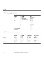
Страница 153: ...Physical Specifications Table A 1 Sun Ultra 1 Series Workstation Physical Specifications U S A Metric Height 4 00 inches 10 15 cm Width 16 44 inches 41 75 cm Depth 17 44 inches 44 30 cm Weight range 2...

Страница 154: ...1 5V 18A 2 3 3V 12 A 3 2 5 to 3 6 V 12 to 8 3 A 4 12V 5 1 A 5 12V 0 3 A Input Power rating 260 W Volt Ampere rating 260 VA Power factor 98 Table A 3 Environmental Limits Operating U S A Operating Metr...

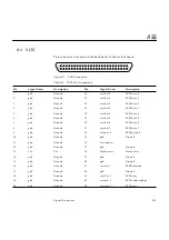
Страница 155: ...1 Keyboard Mouse Connector Table B 1 Keyboard Mouse Pin Assignments Pin Signal Name Description Pin Signal Name Description 1 GND Ground 5 kbd txd Keyboard transmit data 2 GND Ground 6 kbd rxd Keyboa...

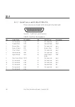
Страница 156: ...nected none 2 Transmit Data TxD 15 Transmit Clock TRxC 3 Receive Data RxD 16 Not connected none 4 Ready To Send RTS 17 Receive Clock RTxC 5 Clear To Send CTS 18 Not connected none 6 Data Set Ready DSR...

Страница 157: ...Connector This connector is located on the back panel of the system board Figure B 3 AUI Connector Table 11 2 AUI Connector Pinouts Pin Function 1 Gnd 2 AUI_CI 3 AUI_DO 4 Gnd 5 AUI_DI 6 Gnd 7 NC 8 Gnd...

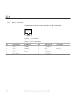
Страница 158: ...is located on the back panel of the system board Figure B 4 TPE Connector Table B 3 TPE Pin Assignments Pin Signal Name Description Pin Signal Name Description 1 tpe0 Transmit 5 No connect 2 tpe1 Tran...

Страница 159: ...d Ground 30 scsi dat 4 SCSI data 4 6 gnd Ground 31 scsi dat 5 SCSI data 5 7 gnd Ground 32 scsi dat 6 SCSI data 6 8 gnd Ground 33 scsi dat 7 SCSI data 7 9 gnd Ground 34 scsi par 0 SCSI parity 0 10 gnd...

Страница 160: ...i msg l SCSI message 22 gnd Ground 47 scsi sel l SCSI select 23 gnd Ground 48 scsi cd l SCSI command 24 gnd Ground 49 scsi req l SCSI request 25 gnd Ground 50 scsi io l SCSI input output Table B 4 SCS...

Страница 161: ...m board Figure B 6 Audio Ports Connector Table B 5 Audio Pin Assignments Headphones Line Out Line In Microphone Tip Left channel Left channel Left channel Left channel Ring center Right channel Right...

Страница 162: ...tor Table 11 3 Parallel Connector Pinouts Pin Description Pin Description 1 nStrobe 14 nAutoFd 2 Data 1 15 nFault 3 Data 2 16 nInit 4 Data 3 17 nSelectln 5 Data 4 18 Signal Ground 6 Data 5 19 Signal G...

Страница 163: ...88 9 mm hard disk drives an optional CD ROM drive or a tape drive and an optional 3 5 inch 88 9 mm diskette drive It has three SBus slots Random access memory RAM is implemented with dynamic single in...

Страница 164: ...ries system Figure C 1 Sun Ultra 1 Series System Block Diagram Audio ports SCSI AUI Parallel port K B Back panel TPE Power supply UPPER CD ROM drive LOWER Diskette drive Fan Speaker UPPER Hard disk dr...

Страница 165: ...am Figure C 2 shows a block diagram of the Sun Ultra 1 Series main logic board Figure C 2 Sun Ultra 1 Series System Board Block Diagram UltraSPARC E DRAM BMX SDB SC_UP Address SYSIO Macio APC SLAVIO S...

Страница 166: ...C 4 Sun Ultra 1 Series Service Manual November 1995 C...

Страница 167: ...it running boot PROM In Sun workstations contains the PROM monitor program a command interpreter used for booting resetting low level configuration and simple test procedures boot PROM diagnostics Th...

Страница 168: ...e random access memory The NVRAM is used to store system variables used by the boot PROM It also contains the system s hostid number and Ethernet address On Board Diagnostics A test that allows you to...

Страница 169: ...un them on SunVTS interface SYSIO Is a bridge chip between UPA and the SBus It also acts as the IO hub providing features such as the IOMMU and streaming buffers to speed up sequential IO access TOD A...

Страница 170: ...Glossary 4 Sun Ultra 1 Series Service Manual November 1995...
Страница 171: ...B 5 serial port B 2 TPE B 4 cover removing 7 1 replacing 7 4 D diagnostic test on board 4 12 disk drive error 4 7 removing 9 2 replacing 9 4 diskette cable 9 9 removing 8 12 replacing 8 14 diskette d...

Страница 172: ...emoving 8 20 replacing 8 22 peripheral cable connection 8 21 physical specifications A 1 POST error reporting 3 3 how to start 3 1 max and min level 3 2 progress 3 3 POST output serial port A 3 6 powe...

Страница 173: ...ard extractor 10 15 SCSI cable backplane removing 8 16 replacing 8 18 SCSI connector B 5 serial port A POST output 3 6 serial port connector B 2 speaker removing 8 8 replacing 8 11 speaker LED cable r...

Страница 174: ...Index 4 Sun Ultra 1 Series Service Manual November 1995...

Страница 175: ...n 3 Which format do you prefer to use Hardcopy On line Please explain 4 Would you be willing to discuss the book with technical publication personnel Email Phone No Please explain 5 Do you have additi...

Страница 176: ...IN THE UNITED STATES BUSINESS REPLY MAIL FIRST CLASS MAIL PERMIT NO 1 MOUNTAIN VIEW CA POSTAGE WILL BE PAID BY ADDRESSEE SUN MICROSYSTEMS INC Attn Manager Hardware Publications MS MPK 14 108 2550 Garc...

Отзывы: