9-10
Sun Ultra 1 Series Service Manual—November 1995
9
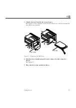
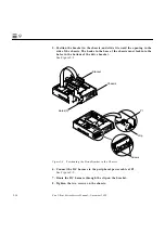
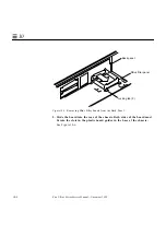
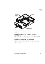
5. Position the bracket in the chassis, and slide it toward the opening in the
side of the chassis. The hooks in the base of the chassis must lock into the
holes in the bottom of the drive bracket.
See Figure 9-9.
Figure 9-9
Positioning the Drive Bracket in the Chassis
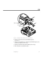
6. Connect the DC harness to the peripheral power cable at P1.
See Figure 9-5.
7. Route the DC harness through the clip on the bracket.
8. Tighten the two screws on the chassis.
Chassis
Bracket
P1
Screws
Clip
Holes (3)
Содержание Ultra 1 140
Страница 6: ......
Страница 8: ...Sun Ultra 1 Series Service Manual November 1995...
Страница 12: ...x Sun Ultra 1 Series Service Manual November 1995 Glossary Glossary 1 Index Index 1...
Страница 23: ...Part1 SystemInformation Product Description page 1 1...
Страница 24: ......
Страница 28: ...1 4 Sun Ultra 1 Series Service Manual November 1995 1...
Страница 30: ......
Страница 46: ...3 14 Sun Ultra 1 Series Service Manual November 1995 3...
Страница 62: ...4 16 Sun Ultra 1 Series Service Manual November 1995 4...
Страница 63: ...Part3 PreparingforService Safety and Tool Requirements page 5 1 Power On and Off page 6 1...
Страница 64: ......
Страница 68: ...5 4 Electron Service Manual November 1995 5...
Страница 72: ......
Страница 108: ...8 32 Sun Ultra 1 Series Service Manual November 1995 8...
Страница 121: ...Part5 SystemBoard System Board and Component Replacement page 10 1...
Страница 122: ......
Страница 147: ...Part6 IllustratedPartsBreakdown Replacement Parts page 11 1...
Страница 148: ......
Страница 152: ......
Страница 166: ...C 4 Sun Ultra 1 Series Service Manual November 1995 C...
Страница 170: ...Glossary 4 Sun Ultra 1 Series Service Manual November 1995...
Страница 174: ...Index 4 Sun Ultra 1 Series Service Manual November 1995...


