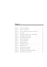
Figures
xiii
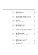
Figure 9-3
Replacing the Disk Drive . . . . . . . . . . . . . . . . . . . . . . . . . . . . . . .
9-4
Figure 9-4
Replacing the EMI Door . . . . . . . . . . . . . . . . . . . . . . . . . . . . . . . .
9-5
Figure 9-5
Drive Bracket . . . . . . . . . . . . . . . . . . . . . . . . . . . . . . . . . . . . . . . . .
9-6
Figure 9-6
Placing the Drive Bracket on Top of the Disk Drive . . . . . . . .
9-7
Figure 9-7
Positioning the CD-ROM/Tape Drive . . . . . . . . . . . . . . . . . . . .
9-8
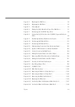
Figure 9-8
Connecting the Cables from the CD-ROM/Tape and Diskette
Drive . . . . . . . . . . . . . . . . . . . . . . . . . . . . . . . . . . . . . . . . . . . . . . . .
9-9
Figure 9-9
Positioning the Drive Bracket in the Chassis. . . . . . . . . . . . . . .
9-10
Figure 9-10
Positioning the Diskette Drive. . . . . . . . . . . . . . . . . . . . . . . . . . .
9-11
Figure 9-11
Positioning the Diskette Drive. . . . . . . . . . . . . . . . . . . . . . . . . . .
9-12
Figure 10-1
Disconnecting Connectors from the System Board . . . . . . . . .
10-3
Figure 10-2
Speaker/LED Connector on the System Board. . . . . . . . . . . . .
10-4
Figure 10-3
Captive Screws on the Back Panel . . . . . . . . . . . . . . . . . . . . . . .
10-4
Figure 10-4
Sliding the System Board Out of the Chassis . . . . . . . . . . . . . .
10-5
Figure 10-5
Removing SBus Filler Panels from the Back Panel . . . . . . . . . .
10-6
Figure 10-6
Sliding the System Board Into The Chassis . . . . . . . . . . . . . . . .
10-7
Figure 10-7
Location of the Serial Port Jumpers . . . . . . . . . . . . . . . . . . . . . .
10-8
Figure 10-8
Identifying Jumper Pins . . . . . . . . . . . . . . . . . . . . . . . . . . . . . . . .
10-9
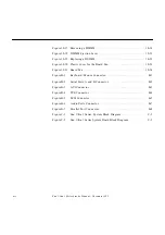
Figure 10-9
NVRAM/TOD . . . . . . . . . . . . . . . . . . . . . . . . . . . . . . . . . . . . . . . . 10-10
Figure 10-10 SBus Slots Location . . . . . . . . . . . . . . . . . . . . . . . . . . . . . . . . . . . . 10-12
Figure 10-11 Removing an SBus Card from Slot 0 or 1. . . . . . . . . . . . . . . . . . 10-13
Figure 10-12 Removing an SBus Card from Slot 2. . . . . . . . . . . . . . . . . . . . . . 10-14
Figure 10-13 Removing the SBus Card Extractor. . . . . . . . . . . . . . . . . . . . . . . 10-15
Figure 10-14 Replacing the SBus Card . . . . . . . . . . . . . . . . . . . . . . . . . . . . . . . 10-16
Figure 10-15 Lock in the SBus Card Retainers, SBus Slots 0 or 1 . . . . . . . . . 10-17
Figure 10-16 Lock in the SBus Card Retainer, SBus Slot 2 . . . . . . . . . . . . . . . 10-18
Содержание Ultra 1 140
Страница 6: ......
Страница 8: ...Sun Ultra 1 Series Service Manual November 1995...
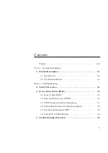
Страница 12: ...x Sun Ultra 1 Series Service Manual November 1995 Glossary Glossary 1 Index Index 1...
Страница 23: ...Part1 SystemInformation Product Description page 1 1...
Страница 24: ......
Страница 28: ...1 4 Sun Ultra 1 Series Service Manual November 1995 1...
Страница 30: ......
Страница 46: ...3 14 Sun Ultra 1 Series Service Manual November 1995 3...
Страница 62: ...4 16 Sun Ultra 1 Series Service Manual November 1995 4...
Страница 63: ...Part3 PreparingforService Safety and Tool Requirements page 5 1 Power On and Off page 6 1...
Страница 64: ......
Страница 68: ...5 4 Electron Service Manual November 1995 5...
Страница 72: ......
Страница 108: ...8 32 Sun Ultra 1 Series Service Manual November 1995 8...
Страница 121: ...Part5 SystemBoard System Board and Component Replacement page 10 1...
Страница 122: ......
Страница 147: ...Part6 IllustratedPartsBreakdown Replacement Parts page 11 1...
Страница 148: ......
Страница 152: ......
Страница 166: ...C 4 Sun Ultra 1 Series Service Manual November 1995 C...
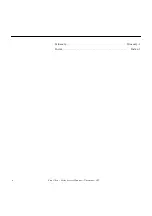
Страница 170: ...Glossary 4 Sun Ultra 1 Series Service Manual November 1995...
Страница 174: ...Index 4 Sun Ultra 1 Series Service Manual November 1995...


