background image

10     

Hyponic®


Operating and Maintenance Manual

Hyponic® Operating and Maintenance Manual


11

www.SumitomoDrive.com


Note:

 Customer should supply parts for setting, securing or removing the shaft.

Fig. 9

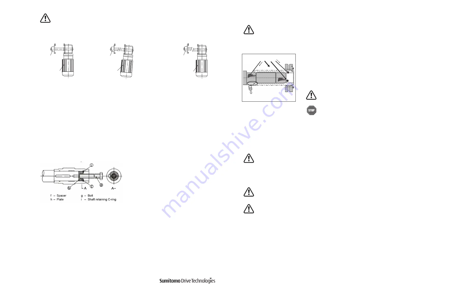
When installing the gearmotor when flange-mounted, ensure that the gearmotor and the 
shaft of the driven machine are properly aligned so that the gearmotor is free from excessive 
force 

(Figure 8)

.

Fig. 8

Hyponic® hollow
shaft model

Bearing unit

Poor concentricity of driven 

shaft and mounting flange

Incorrect

Hyponic® hollow
shaft model

Bearing unit

Poor perpendicularity of driven shaft 

center and mounting flange surface

Incorrect

Hyponic® hollow
shaft model

Bearing unit

Correct

Shrink Disc

1

Clean and degrease contact surfaces; reducer shaft and bore, and the machine 
driven shaft.

Apply Molykote 321 or an equivalent dry film lubricant to the driven shaft 
projection opposite from the shrink disc. 

Align the driven shaft with the reducer hollow bore and carefully slide unit onto the driven shaft.

If the fit is tight, strike on the reducer hollow bore with a mallet to assist in the assembly.

If using a soft non-metallic mallet during installation, strike 

only

 against the unit’s steel hollow bore. 

Do not


strike the reducer housing or oil seal. Damage to the bearings, the housing, and/or the seals may occur.

Note:

 If the fit is tight, use a jig such as the one shown in 

Figure 5

 to ease assembly. 

Sumitomo does not supply a 

mounting jig. This information is provided for reference only.

Never tighten locking screws before shaft installation. Inner ring may become permanently contracted even 
at low tightening torques.

Ensure that all power switches are locked out before installing or removing shrink disc. Wear safety glasses 
and protective clothing at all times

Before placing unit onto driven shaft, 

do not apply grease, oil, or anti-seize grease

 to the entire driven 

shaft or to the bore of the shrink disc. Use of these friction-minimizing products will adversely affect the 
ability of the unit to transmit torque. 

3

Remove any wooden spacers that may have been used during shipping. Lightly lubricate the hub outside diameter 
and shrink disc bore.

Degrease these areas

Apply Molykote 321  
to this shaft area only

For food grade application, use food grade dry film lubricant.

Do not apply any friction minimizing compound to the driven shaft at 
or near the shrink disc


d.

 Removing the Shaft

Do not apply excessive force to the unit and shaft. Using a jig as shown in 

Figure 9

 will facilitate 

removal of the shaft.

Содержание Hyponic 1120

Страница 1: ...Operating and Maintenance Manual 07 020 60 002 Hyponic O M 2019 Hyponic...

Страница 2: ...plosion proof motor a technician with electrical expertise should supervise the transport installation plumbing wiring operation maintenance and inspection of the equipment otherwise explosion ignitio...

Страница 3: ...is not for immediate use please note the following points when storing it Store the product indoors in a clean dry location External Rust Prevention Rust prevention oil is applied when shipping from...

Страница 4: ...ructions for proper bolt tightening torque Important If the bolt is tightened when the fitting is not inserted uneven tightening will result causing damage to the internal bearing and other components...

Страница 5: ...nufacturer recommendation and keep tension angle perpendicular to the shaft Table 2 Flange Mount Bolt Size Flange or Foot Mount Solid Shaft Type When mounting connected equipment do not apply impact o...

Страница 6: ...causing vibration or grease leak If the effective length of driven shaft is short the key and the keyway may be damaged If the hollow shaft end face is hit with a metal hammer or the driven shaft was...

Страница 7: ...only against the unit s steel hollow bore Do not strike the reducer housing or oil seal Damage to the bearings the housing and or the seals may occur Note If the fit is tight use a jig such as the on...

Страница 8: ...9 105 2327 263 Final Torque in lb Nm 43 4 9 105 11 8 266 30 531 60 885 100 2221 251 Socket Size mm 8 10 13 17 19 24 Table 3 Shrink Disc Size and Tightening Torque Mount the torque arm on the driven ma...

Страница 9: ...rmal Brake Action 230V or 575V Brake Fig 13 b Fast Brake Action 230V Brake Fig 13 c Normal Brake Action 460V Brake Fig 13 d Fast Brake Action 460V or 575V Brake Tighten both pairs of nuts against the...

Страница 10: ...ake Action 460V or 575V Brake Wiring Connections for VFD Inverter Models FB 01A1 through FB 15E 230 460V 60Hz or 575V 60Hz VFD VFD VFD VFD VFD VFD VFD VFD a Always ground the motor terminal box or fra...

Страница 11: ...meplate voltage rating 10 3 The ambient temperature around the unit is too high Table 8 Trial Run Precautions Daily Inspection and Maintenance 1 Inspect the gearmotor daily for each of the items liste...

Страница 12: ...ed at a rate greater than the Allowable Brake Work Capacity E0 the brake performance may degrade or become inoperable 1 Also applies to wiring where brake is powered separately from the motor leads Br...

Страница 13: ...olt 16 fastens the brake shoe 8 gap adjusting shims 17 and spacer 18 onto the stationary core 1 The armature plate 4 is kept from rotation by the restraining bolt 16 but moves axially by electromagnet...

Страница 14: ...not excessively worn or gap G is normal all the mounting screws are securely tightened b Manual brake release procedure FB 1D FB 2D FB 1E FB 1HE FB 2E and FB 3E brakemotors are equipped with a one tou...

Страница 15: ...a few times to check the brake performance If no abnormalities are detected replace waterproof cover 24 waterproof seal 25 V Ring 23 fan 15 retaining ring 14 cover 13 shifting pins 5 and brake releas...

Страница 16: ...Armature 5 Shifting Pin 6 Brake Release Lever 7 Retaining Clip 8 Brake Shoe 9 Brake Lining 10 Leaf Spring 11 Hub 12 C type Retaining Ring 13 Cover 14 C type Retaining Ring 15 Fan 16 Gap Adjusting Nut...

Страница 17: ...eal 26 and waterproof cover 25 c Insert a gap gage into the space between the stationary core 1 and armature plate 4 and rotate the nut 16 at the tip of the stud bolt 19 clockwise until the gap measur...

Страница 18: ...ly open Replace Stator coil open Repair by rewinding or replacing stator assembly Stator and rotor touching due to bearing housing wear Replace the bearing and bracket Table 18 Quick Troubleshooting G...

Страница 19: ...vailable from three phase power supply Measure power supply voltage and check for defective circuit Protective device has tripped Eliminate cause and reset Damaged or burned motor winding Repair or re...

Страница 20: ...36 Hyponic Operating and Maintenance Manual Hyponic Operating and Maintenance Manual 37 www SumitomoDrive com...

Страница 21: ...38 Hyponic Operating and Maintenance Manual Hyponic Operating and Maintenance Manual 39 www SumitomoDrive com Notes Notes...

Страница 22: ...rters Japan Sumitomo Heavy Industries Ltd PowerTransmission Controls Group ThinkParkTower 1 1 Osaki 2 chome Shinagawa ku Tokyo 141 6025 Japan Tel 81 36 737 2511 Fax 81 36 866 5160 07 020 60 002 Hyponi...

Отзывы: