26
Hyponic®
Operating and Maintenance Manual
Hyponic® Operating and Maintenance Manual
27
www.SumitomoDrive.com
If the brake lining is so heavily worn that gap adjustment is required, follow these steps:
a)
Remove shifting pins (5) and brake release lever (6).
b)
Remove the cover (13). Remove fan (15) by removing retaining ring (14). Remove V-Ring (23) waterproof seal
(25) and waterproof cover (24).
c)
Measure the gap size to confirm the deviation from the specification value. The minimum adjustable setting is
no less than the thickness of the Gap Adjusting Shim shown in
Table 13
.
d)
Loosen the restraining bolt (16) and remove parts (16), (8), (17), and (18) as a set. Be careful not to remove only
the bolt (16) and lose the shims (17).
e)
Decrease the number of shims in use according to the degree of wear (
Note:
Retain the removed shims for use
during the brake lining replacement procedure). Reassemble parts (16), (8), (17) and (18) as a set.
f)
Once reassembled, check gap G. If the gap size is still too large, adjust the number of shims again.
g)
After completing the gap adjustment, turn the system power on and off a few times to check the brake
performance.
h)
Replace waterproof cover (24), waterproof seal (25), V-Ring (23), fan (15), retaining ring (14), cover (13), shifting
pins (5), and brake release lever (6).
5. Gap Adjustment
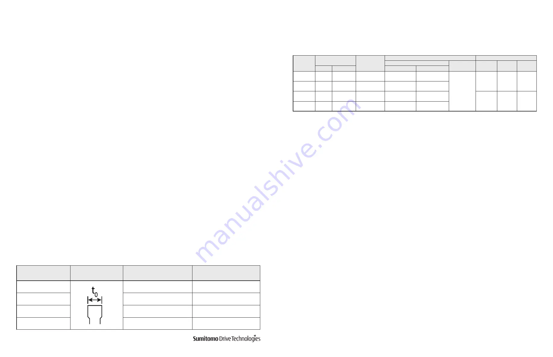
Follow these steps to replace the brake lining when its thickness has reached the allowable limit shown in
Table 14
,
or when sleeve adjustment is no longer an effective means of gap adjustment:
a)
Remove shifting pins (5) and brake release lever (6).
b)
Remove the cover (13). Remove fan (15) by retaining ring (14). Remove V-Ring (23) waterproof seal (25) and
waterproof cover (24).
c)
Loosen the restraining bolt (16) and remove parts (16), (17), (18) and (8) as a set.
d)
Remove the brake lining (9), taking care to prevent the leaf spring (10) from coming off.
e)
Install the new brake lining, taking care not to damage or remove the leaf spring (10). Ensure that the lining
moves smoothly along the hub (11).
f)
Replace any gap adjusting shims removed and retained from previous gap adjustments. Then reinstall parts
(16), (17), (18) and (8) as a set.
g)
Measure gap G. Readjust if the gap is not within the specification value range.
h)
Turn the system power on and off a few times to check the brake performance. If no abnormalities are detected,
replace waterproof cover (24), waterproof seal (25), V-Ring (23), fan (15), retaining ring (14), cover (13), shifting
pins (5) and brake release lever (6).
6. Brake Lining Replacement
Table 14. Brake Lining Size
Brake Type
Brake lining dimension
Initial Thickness
t
0
, in.
(mm)
Allowable Thickness
t
0
, in.
(mm)
FB-1D
0.276
(7.0)
0.236
(6.0)
FB-2D, FB-1E
0.347
(8.8)
0.307
(7.8)
FB-1HE, FB-2E, FB-3D
0.354
(9.0)
0.315
(8.0)
FB-3E
0.398
(10.4)
0.331
(8.4)
Brake Models FB-5E, FB-8E, FB-10E, and FB-15E
Table 15
lists the standard specifications for Models FB-5E, FB-8E, FB-10E, and FB-15E.
a) Construction
Figures 17-a and 17-b
illustrate the construction of the brake. Among the brake parts, the stationary core (1),
solenoid coil (20), and stud bolt (19) constitute an integral subassembly unit. The stud bolt (19) keeps the armature
plate (4) from rotating, but the plate moves axially by electromagnetic attraction and the tension of the pressure
spring (2). The adjusting washer (18) and spring washer (17) hold the brake shoe (8) against the nut (16) at all times.
The brake lining (9) is fit to the hub (11), which is secured to the motor shaft with a key.
1. Standard Brakemotor Specifications
2. Construction and Operating Principles
Table 15. Models FB-5E, FB-8E, FB-10E, and FB-15E Standard Specifications
Notes:
Above table applies to standard brake specification under standard brake torque. Special brakes may perform differently from those shown.
Initial
brake torque may be lower than specified brake torque. If this is the case, under light load start and stop the motor to wear-in the braking surface. To improve
performance for positioning accuracy or lifting applications, consider using fast braking action circuit. If the brake is operated at a rate greater than the Allowable
Brake Work Capacity, E0, the brake performance may degrade or become inoperable.
[1]
Also applies to wiring where brake is powered separately from the motor leads.
Brake
Model
Motor Capacity
Standard Brak-
ing Torque
ft - lbs
(N - m)
Braking Delay Time (sec)
Brake Work Capacity
Normal Braking Action
Fast Braking
Action
Allowable
E
0
(J/min)
Gap Adjust
(x 10
7
J)
Total
E
1
(x 10
7
J)
HP x 4P
kW x 4P
Standard Wiring
Inverter Wiring
[1]
FB-5E
5
3.7
30 (40)
1.1 ~ 1.3
0.4 ~ 0.5
0.02 ~ 0.04
6900
57.4
382.8
FB-8E
7.5
5.5
40 (55)
1.0 ~ 1.2
0.3 ~ 0.4
FB-10E
10
7.5
59 (80)
1.8 ~ 2.0
0.6 ~ 0.7
10800
110.2
551.1
FB-15E
15
11
80 (110)
1.6 ~ 1.8
0.5 ~ 0.6


