Troubleshooting
31
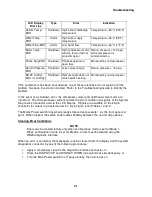
LCD Display
First Line
Type
Error
Indication
Helium Temp-
ERR
Shutdown High helium discharge
temperature
Temperature > 93°C (200°F)
Water Temp-
ERR
Alarm
High water supply
temperature.
Temperature > 35°C (95°F).
Water Flow-ERR
Alarm
Low water flow
Temperature > 46°C (115°F)
Motor Temp-
ERR
Shutdown High compressor motor
winding temp (internal
protector open)
Return Pressure > 140 psig
while compressor is
commanded on.
Phase Seq-ERR
Shutdown Phase sequence or
open fuse
Monitored by microprocessor
Return Pressure-
ERR
Shutdown Loss of gas charge
Return pressure < 15 psig.
DB-25 Config1-
ERR (or Config2)
Shutdown Remote cable does not
match switch setting
Monitored by microprocessor
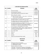
If the compressor has been shut down by one of these interlocks, do not restart until the
problem has been found and corrected. Refer to the Troubleshooting Guide to identify the
problem.
In the event of a shutdown error, the compressor motor and cold head valve motor are
turned off. The microprocessor will annunciate the error condition via signals at the System
Diagnostics Connector and via the LCD Display. Signals are available on the 25-pin
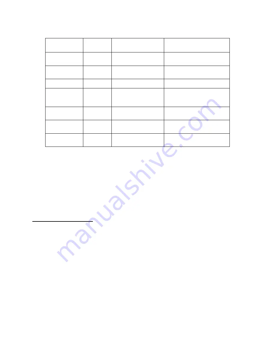
connector for output to an external device. See Figure 2 and Tables 1 and 2.
The Mains Power switch trips when steady-state current exceeds 1.2 x the front panel set
point. When tripped, the switch knob locates halfway between the on and off positions.
Clearing Error Conditions
NOTE
Errors can be cleared locally only when configuration mode is set for Mode 1.
When configuration mode is set for Mode 2, errors must be cleared using the
DB25 diagnostic interface.
When an error is corrected, the message(s) can be cleared from the display and the system
diagnostics connector by any of the following procedures:
•
Apply a momentary signal to the diagnostic interface connector, or
•
Press the DISPLAY UP and DISPLAY DOWN (arrow) buttons simultaneously, or
•
Turn the Main Power switch to off, pause briefly, then turn back on
Содержание F-70H
Страница 2: ......
Страница 8: ...4 This page is intentionally blank...
Страница 10: ...6 This page is intentionally blank...
Страница 12: ...8 This page is intentionally blank...
Страница 14: ...10 This page is intentionally blank...
Страница 28: ...24 This page is intentionally blank...
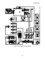
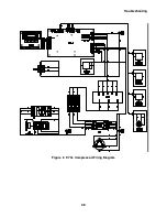
Страница 40: ...Troubleshooting 36 Figure 4 F 70H Compressor Wiring Diagram...
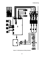
Страница 41: ...Troubleshooting 37 Figure 5 F 70H Compressor Wiring Schematic...
Страница 42: ...Troubleshooting 38 Figure 6 F 70L Compressor Wiring Diagram...
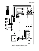
Страница 43: ...Troubleshooting 39 Figure 7 F 70L Compressor Wiring Schematic...
Страница 46: ...42 This page is intentionally blank...

