DESCRIPTION
11
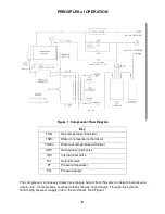
Components
Adsorber
- The adsorber removes any oil and moisture the gas is carrying which did not drop
out in the separator. The adsorber has a finite life and must be replaced every 30,000 operating
hours.
Atmosphere Relief Valve [ARV]
– The pressure relief valve prevents the compressor from
operating at an unsafe pressure by venting to the atmosphere.
Bulk Oil Separator
- Removes much of the entrained oil from the gas stream. This unit needs
no servicing or replacement.
Cold Head Power Receptacle
- Mounted on the front panel for connecting a cable to supply
electrical power from the compressor to the cold head.
Compressor Capsule
- Helium, scroll compressor with a hermetically sealed motor.
Compressor High Temperature Motor Protector Switch
- Located inside the compressor
motor, the switch senses compressor motor temperature and stops the motor if the temperature
is too high. The switch resets after cool down.
Electrical Chassis
- The electrical box contains electrical components and connections and
distributes power to all system circuits.
Final Oil Separator
- Removes most of the remaining entrained oil from the gas stream. This
unit needs no servicing or replacement.
Fuses
– Three (3) time delay, class CC fuses, located inside the electrical chassis box,
protect
the transformer. Three (3) time delay, 5x20 mm, IEC Type T fuses, located on the printed
circuit board inside the electrical chassis box, protect the cold head supply circuit.
Heat Exchanger
- Uses water to cool the high-pressure helium refrigerant and the
compressor’s lubricating oil.
Helium Charge
- A size 4, male (4M), Aeroquip coupling located on the front of the compressor
is used for charging or venting helium gas refrigerant.
Helium Supply and Helium Return Pressure Couplings
– Both supply (high pressure) and
return (low pressure) are self-sealing, size 8, male (8M), Aeroquip, bulkhead couplings and are
the points of connection on the front panel for the gas lines.
Internal Relief Valve [IRV]
- The internal relief valve opens to allow the compressor to be
operated in the stand-alone mode or when the system gas lines are disconnected, to avoid
overloading the motor.
Mains Power Switch
- Mounted on the front panel, it provides a means to disconnect power
and it protects the compressor from electrical overload. This device is labeled Main Power.
Oil Capillary
- The capillary returns oil collected in the oil separator sump to the compressor for
recycling.
Oil Filter
- Filters in the oil lines protect the oil return capillary and the orifices.
Содержание F-70H
Страница 2: ......
Страница 8: ...4 This page is intentionally blank...
Страница 10: ...6 This page is intentionally blank...
Страница 12: ...8 This page is intentionally blank...
Страница 14: ...10 This page is intentionally blank...
Страница 28: ...24 This page is intentionally blank...
Страница 40: ...Troubleshooting 36 Figure 4 F 70H Compressor Wiring Diagram...
Страница 41: ...Troubleshooting 37 Figure 5 F 70H Compressor Wiring Schematic...
Страница 42: ...Troubleshooting 38 Figure 6 F 70L Compressor Wiring Diagram...
Страница 43: ...Troubleshooting 39 Figure 7 F 70L Compressor Wiring Schematic...
Страница 46: ...42 This page is intentionally blank...


