Maintenance
18
10.
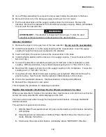
Leak check the Aeroquip couplings using the Leak Check procedure in this manual
This completes the charging procedure.
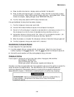
Venting Procedure to Adjust the Equalization Pressure
NOTE
This venting procedure is not to be used for gas cleanup of the compressor.
To vent helium gas from the system:
1.
Stop the compressor.
2.
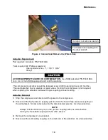
Be sure the valve on the charge and vent tool, P/N 267191A, is closed. Using two
wrenches, install this tool on the 4M Aeroquip helium charge port.
3. Slowly
open the valve on the charge and vent tool. Vent the system until the required
equalization pressure is attained. See Specifications in the F-70 Operating Manual. Close
the valve on the tool.
4.
Using two wrenches, remove the charge and vent tool from the compressor.
This completes the venting procedure to adjust the equalization pressure.
Gas Cleanup
Tools required: 2 adapter fittings with valve, 8F Aeroquip, 255919B2.
Open-end wrenches, 1", 1 1/8" and 1 3/16".
Helium gas cylinder with pressure regulator and charge line.
If the equalization pressure shown by the compressor’s pressure gauge is less than 1.4 bar
(20 psig), gas cleanup of the compressor is required. Look for and repair helium leaks. Perform
gas cleanup.
If system components are connected and the equalization pressure of the system is less than
1.4 bar (20 psig), check for leaks. Repair leaks. Perform gas cleanup of the system.
PREVENT EQUIPMENT DAMAGE.
Never pull a vacuum on the compressor or
on the cold head. The motors will short circuit if started.
AVOID INJURY.
Extreme cold can cause frostbite. When handling system
components, be careful not to touch any frosted parts.
AVOID INJURY.
Do not splash cryogenic liquids on any areas of clothing or
exposed skin. Damage to skin tissue will result. Always wear eye protection.
Содержание F-70H
Страница 2: ......
Страница 8: ...4 This page is intentionally blank...
Страница 10: ...6 This page is intentionally blank...
Страница 12: ...8 This page is intentionally blank...
Страница 14: ...10 This page is intentionally blank...
Страница 28: ...24 This page is intentionally blank...
Страница 40: ...Troubleshooting 36 Figure 4 F 70H Compressor Wiring Diagram...
Страница 41: ...Troubleshooting 37 Figure 5 F 70H Compressor Wiring Schematic...
Страница 42: ...Troubleshooting 38 Figure 6 F 70L Compressor Wiring Diagram...
Страница 43: ...Troubleshooting 39 Figure 7 F 70L Compressor Wiring Schematic...
Страница 46: ...42 This page is intentionally blank...


