Maintenance
15
5.
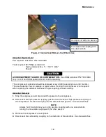
Use a Phillips screwdriver to remove the two screws holding the adsorber to the base.
6.
Remove the locknut on the Aeroquip supply coupling on the front panel.
7.
Pull the adsorber back until the supply coupling clears the front panel. Remove the
adsorber. Remove the lockwasher from the Aeroquip supply coupling. Retain all hardware
to reuse with the new adsorber.
AVOID INJURY.
The adsorber is charged with helium gas. Follow the used
adsorber venting procedure for safe disposal of the used adsorber.
Adsorber Installation
1.
Remove the caps from the gas lines of the new adsorber.
Do not vent the new adsorber.
2.
Install the lock washer on to the supply coupling of the new adsorber. Insert the supply
coupling through the front panel and position the adsorber.
3.
Insert and tighten the screws to secure the new adsorber to the base.
4.
Install the Nylon washer and the locknut on the supply coupling. Torque the locknut to 54
Nm (40-ft. lbs.).
5.
Connect the adsorber’s self-sealing coupling on its inlet side to the oil separator’s outlet
coupling. With two wrenches, torque the Aeroquip coupling to 47 ± 7 Nm (35 ± 5 ft. lbs.).
6.
Reconnect the supply (red) gas line to the supply coupling on the compressor. Torque the
coupling to 47 ± 7 Nm (35 ± 5-ft. lbs.).
7.
Using Snoop
®
, leak check all Aeroquip couplings just completed. Wipe off the Snoop
®
to
prevent rusting. See the Leak Check procedure in Maintenance in this manual.
8.
Check the equalization pressure. See Specifications in the Operating Manual.
9.
Reinstall the compressor’s cover panel.
This completes the procedure for replacing an adsorber.
Register New Adsorber (30,000 hour life) (for firmware versions 1.7 or later)
When a new adsorber is installed, the adsorber timer must be reset to 30,000 hours so that the
correct remaining adsorber life will be displayed on the LCD.
The timer can be reset either through the front panel control buttons or through the RS232
terminal interface.
Through the front panel control buttons:
1.
With the Main Power switch turned off, press and hold all four control buttons below the
LCD window.
2.
Keep these buttons held and turn the Main Power Switch ON to enter “Service Level”
mode. Release the buttons.
3.
Scroll using the arrow control buttons until display shows “NEW ADS? ON=Yes.”
Содержание F-70H
Страница 2: ......
Страница 8: ...4 This page is intentionally blank...
Страница 10: ...6 This page is intentionally blank...
Страница 12: ...8 This page is intentionally blank...
Страница 14: ...10 This page is intentionally blank...
Страница 28: ...24 This page is intentionally blank...
Страница 40: ...Troubleshooting 36 Figure 4 F 70H Compressor Wiring Diagram...
Страница 41: ...Troubleshooting 37 Figure 5 F 70H Compressor Wiring Schematic...
Страница 42: ...Troubleshooting 38 Figure 6 F 70L Compressor Wiring Diagram...
Страница 43: ...Troubleshooting 39 Figure 7 F 70L Compressor Wiring Schematic...
Страница 46: ...42 This page is intentionally blank...

