PRINCIPLES of OPERATION
9
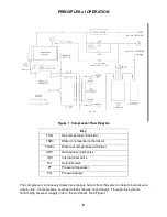
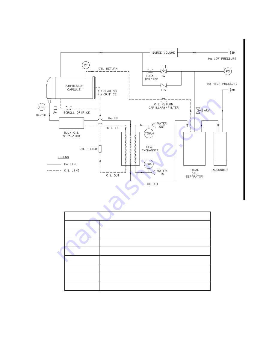
Figure 1 Compressor Flow Diagram
Key
TSG
Gas temperature thermistor
TSWi
Water-in temperature thermistor
TSWo
Water-out temperature thermistor
ARV
Atmospheric relief valve
IRV
Internal relief valve
SV
Solenoid valve
PT
Pressure transducer
PG
Pressure gauge
The compressor continuously draws low-pressure helium from the system’s helium low pressure
(return) line. It compresses, cools and cleans the gas, then delivers it through the system’s
helium high pressure (supply) line to the cold head. See Figure 1.
Содержание F-70H
Страница 2: ......
Страница 8: ...4 This page is intentionally blank...
Страница 10: ...6 This page is intentionally blank...
Страница 12: ...8 This page is intentionally blank...
Страница 14: ...10 This page is intentionally blank...
Страница 28: ...24 This page is intentionally blank...
Страница 40: ...Troubleshooting 36 Figure 4 F 70H Compressor Wiring Diagram...
Страница 41: ...Troubleshooting 37 Figure 5 F 70H Compressor Wiring Schematic...
Страница 42: ...Troubleshooting 38 Figure 6 F 70L Compressor Wiring Diagram...
Страница 43: ...Troubleshooting 39 Figure 7 F 70L Compressor Wiring Schematic...
Страница 46: ...42 This page is intentionally blank...


