SECTION 6
TS32 USER MANUAL
75
6.8
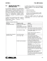
TROUBLESHOOTING—
INTRODUCTION
The information contained in the Troubleshooting
Guide has been compiled from field report data and
factory experience. It contains symptoms and usual
causes for the described problems. However, DO
NOT assume that these are the only problems that
may occur. All available data concerning a problem
should be systematically analyzed before
undertaking any repairs or component replacement
procedures.
In addition to the Troubleshooting Guide, consult the
Supervisor Controller manual for additional
troubleshooting guidelines pertaining to the
Supervisor Controller.
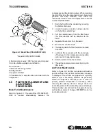
A detailed visual inspection is worth performing for
almost all problems and may avoid unnecessary
additional damage to the compressor. Always
remember to:
1. Check for loose wiring.
2. Check for damaged piping.
3. Check for parts damaged by heat or an elec-
trical short circuit, usually apparent by discol-
oration or a burnt odor.
Should your problem persist after making the
recommended check, consult your nearest Sullair
representative.
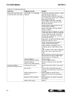
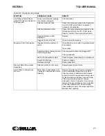
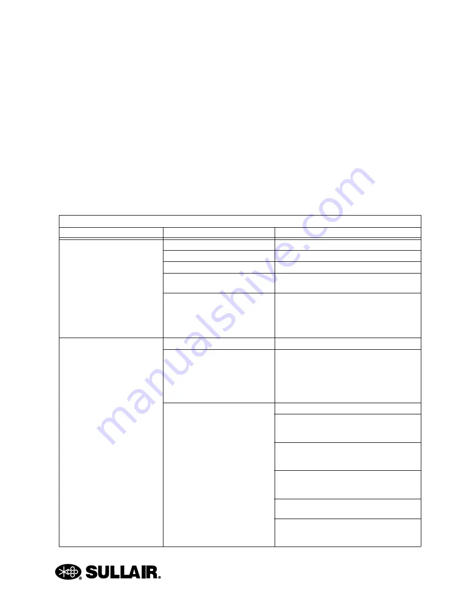
Table 6-2: Troubleshooting Guide
SYMPTOM
PROBABLE CAUSE
REMEDY
Compressor will not start
Main disconnect switch open
Close switch.
Line fuse blown
Replace fuse.
Control Transformer Fuse Blown
Replace fuse.
Motor Starter Overloads Tripped
Reset. Should trouble persist, check whether
motor starter contacts are functioning properly.
Low Incoming Line Voltage
Check voltage. Should voltage check low,
consult power company.
Replace Supervisor display module if no
display or erratic display.
Compressor Shuts Down With
Air Demand Present
Loss of control voltage
Check incoming power.
Low incoming voltage
Check control fuses and wiring.
Consult power company. The Sullair
Supervisor will provide indication of most
maintenance problems if control power has not
been lost. Shutdowns will occur upon a faulty
condition or a bad sender condition.
Excessive operating pressure
Check maximum P2 pressure setting.
HIGH PRESS P1 display; Max P1 pressure
may be set too low. Consult factory for
recalibration.
Defective solenoid valve; solenoid valve
should cause inlet to unload when unload
pressure is exceeded. Repair if defective.
Defective blowdown valve; blowdown valve
should open when in the unload mode. Repair
if defective.
Open or shorted P1, P2, P3 or P4 sender
message; replace sender indicated.
Operating lever of inlet butterfly valve is loose
on valve shaft. Reposition the valve plate and
tighten lever set screw.
Содержание TS32 AC
Страница 10: ...NOTES 10...
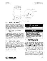
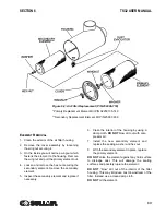
Страница 12: ...TS32 USER MANUAL SECTION 2 12 Figure 2 1 Sullair Series TS32 Rotary Screw Compressor Air cooled Typical...
Страница 13: ...SECTION 2 TS32 USER MANUAL 13 Figure 2 2 Sullair Series TS32 Rotary Screw Compressor Water cooled Typical...
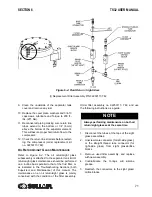
Страница 15: ...SECTION 2 TS32 USER MANUAL 15 Figure 2 3 Compressor Piping and Instrument Diagram Typical...
Страница 16: ...TS32 USER MANUAL SECTION 2 16 Figure 2 4 Compressor Cooling and Lubrication System Air cooled...
Страница 17: ...SECTION 2 TS32 USER MANUAL 17 Figure 2 5 Compressor Cooling and Lubrication System Water cooled...
Страница 18: ...TS32 USER MANUAL SECTION 2 18 Figure 2 6 Compressor Discharge System Air cooled 200 350HP...
Страница 19: ...SECTION 2 TS32 USER MANUAL 19 Figure 2 7 Compressor Discharge System Water cooled 200 350HP...
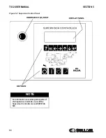
Страница 20: ...TS32 USER MANUAL SECTION 2 20 Figure 2 8 Control System START Typical...
Страница 21: ...SECTION 2 TS32 USER MANUAL 21 Figure 2 9 Control System MODULATION Typical...
Страница 22: ...TS32 USER MANUAL SECTION 2 22 Figure 2 10 Control System UNLOAD Typical...
Страница 23: ...SECTION 2 TS32 USER MANUAL 23 Figure 2 11 Control System FULL LOAD Typical...
Страница 26: ...TS32 USER MANUAL SECTION 2 26 Figure 2 12 Compressor Air Inlet System...
Страница 30: ...TS32 USER MANUAL SECTION 3 30 Figure 3 2 Identification Air Cooled 02250126 376 R02...
Страница 32: ...TS32 USER MANUAL SECTION 3 32 Figure 3 2 Identification Water Cooled 02250126 378 R03...
Страница 34: ...TS32 USER MANUAL SECTION 3 34 Figure 3 3 Piping and Instrumentation Diagram Air Cooled 02250179 499 R01...
Страница 38: ...TS32 USER MANUAL SECTION 3 38 Figure 3 5 Piping and Instrumentation Diagram Remote Air Cooled 02250179 498 R01...
Страница 42: ...TS32 USER MANUAL SECTION 3 42 Figure 3 6 Piping and Instrumentation Diagram Water Cooled 02250179 496 R01...
Страница 46: ...TS32 USER MANUAL SECTION 3 46 Figure 3 7 Wiring Diagram Water Cooled Wye Delta 02250178 841 R01...
Страница 48: ...TS32 USER MANUAL SECTION 3 48 Figure 3 8 Wiring Diagram Air Cooled Full Voltage 02250178 845 R01...
Страница 50: ...TS32 USER MANUAL SECTION 3 50 Figure 3 9 Wiring Diagram Air Cooled SSRV 02250178 844 R03...
Страница 52: ...TS32 USER MANUAL SECTION 3 52 Figure 3 10 Wiring Diagram Remote Air Cooled Wye Delta 02250178 836 R01...
Страница 54: ...NOTES 54...
Страница 78: ...NOTES 78...
Страница 79: ...NOTES 79...


