
Section 6
67
TS32 USER MANUAL
MAINTENANCE
6.1
GENERAL
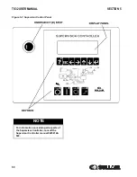
As you proceed in reading this section, it will be easy
to see that the Maintenance Program for the air
compressor is quite minimal yet important. The use
of the service indicators provided for the fluid filter,
air filter and fluid separator, will alert you when
service maintenance is required. When the
maintenance message is displayed by the
Supervisor Controller™, maintenance for that
specific item is required. See instructions for each
item in
, Parts Replacement and
Adjustment procedures.
6.2
DAILY OPERATION
Prior to starting the compressor, it is necessary to
check the fluid level in the sump. Should the level be
low, simply add the necessary amount. If the addition
of fluid becomes too frequent, a simple problem has
developed which is causing this excessive loss. See
the
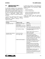
Section 6.8: Troubleshooting— Introduction
under Excessive Fluid Consumption for a probable
cause and remedy.
After a routine start has been made, observe the
Supervisor control panel and be sure it monitors the
correct readings for that particular phase of
operation. After the compressor has warmed up, it is
recommended that a general check of the overall
compressor and Supervisor be made to assure that
the compressor is running properly.
6.3
MAINTENANCE AFTER
INITIAL 50 HOURS OF
OPERATION
After the initial 50 hours of operation, a few
maintenance requirements are needed to rid the
system of any foreign materials if any. Perform the
following maintenance operations to prevent
unnecessary problems.
1. Clean the return line strainers.
2. Clean the return line orifices.
3. Change the fluid filter element
4. Clean the control line filters or strainers
6.4
MAINTENANCE EVERY 1000
HOURS
Every 1000 hours of operation, it will be necessary to
perform the following:
1. Clean the return line strainers.
2. Lubricate the Sullicon Control linkage.
3. Replace the fluid filter element.
6.5
FLUID CHANGE
Standard models are filled with the long life lubricant
Sullube.
Sullube should be changed under the following
conditions, whichever occurs first:
1. Every 8000 hours.
2. Once a year.
3. As indicated by fluid analysis.
WARNING
DO NOT remove caps, plugs, and/or other
components when compressor is running or
pressurized. Stop compressor and relieve all
internal pressure before doing so.
Содержание TS32 AC
Страница 10: ...NOTES 10...
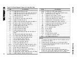
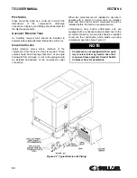
Страница 12: ...TS32 USER MANUAL SECTION 2 12 Figure 2 1 Sullair Series TS32 Rotary Screw Compressor Air cooled Typical...
Страница 13: ...SECTION 2 TS32 USER MANUAL 13 Figure 2 2 Sullair Series TS32 Rotary Screw Compressor Water cooled Typical...
Страница 15: ...SECTION 2 TS32 USER MANUAL 15 Figure 2 3 Compressor Piping and Instrument Diagram Typical...
Страница 16: ...TS32 USER MANUAL SECTION 2 16 Figure 2 4 Compressor Cooling and Lubrication System Air cooled...
Страница 17: ...SECTION 2 TS32 USER MANUAL 17 Figure 2 5 Compressor Cooling and Lubrication System Water cooled...
Страница 18: ...TS32 USER MANUAL SECTION 2 18 Figure 2 6 Compressor Discharge System Air cooled 200 350HP...
Страница 19: ...SECTION 2 TS32 USER MANUAL 19 Figure 2 7 Compressor Discharge System Water cooled 200 350HP...
Страница 20: ...TS32 USER MANUAL SECTION 2 20 Figure 2 8 Control System START Typical...
Страница 21: ...SECTION 2 TS32 USER MANUAL 21 Figure 2 9 Control System MODULATION Typical...
Страница 22: ...TS32 USER MANUAL SECTION 2 22 Figure 2 10 Control System UNLOAD Typical...
Страница 23: ...SECTION 2 TS32 USER MANUAL 23 Figure 2 11 Control System FULL LOAD Typical...
Страница 26: ...TS32 USER MANUAL SECTION 2 26 Figure 2 12 Compressor Air Inlet System...
Страница 30: ...TS32 USER MANUAL SECTION 3 30 Figure 3 2 Identification Air Cooled 02250126 376 R02...
Страница 32: ...TS32 USER MANUAL SECTION 3 32 Figure 3 2 Identification Water Cooled 02250126 378 R03...
Страница 34: ...TS32 USER MANUAL SECTION 3 34 Figure 3 3 Piping and Instrumentation Diagram Air Cooled 02250179 499 R01...
Страница 38: ...TS32 USER MANUAL SECTION 3 38 Figure 3 5 Piping and Instrumentation Diagram Remote Air Cooled 02250179 498 R01...
Страница 42: ...TS32 USER MANUAL SECTION 3 42 Figure 3 6 Piping and Instrumentation Diagram Water Cooled 02250179 496 R01...
Страница 46: ...TS32 USER MANUAL SECTION 3 46 Figure 3 7 Wiring Diagram Water Cooled Wye Delta 02250178 841 R01...
Страница 48: ...TS32 USER MANUAL SECTION 3 48 Figure 3 8 Wiring Diagram Air Cooled Full Voltage 02250178 845 R01...
Страница 50: ...TS32 USER MANUAL SECTION 3 50 Figure 3 9 Wiring Diagram Air Cooled SSRV 02250178 844 R03...
Страница 52: ...TS32 USER MANUAL SECTION 3 52 Figure 3 10 Wiring Diagram Remote Air Cooled Wye Delta 02250178 836 R01...
Страница 54: ...NOTES 54...
Страница 78: ...NOTES 78...
Страница 79: ...NOTES 79...


