TS32 USER MANUAL
SECTION 4
56
W
ATER
-C
OOLED
C
OMPRESSORS
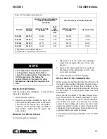
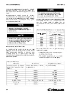
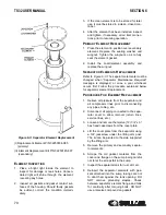
• Water-cooled compressors require a cool-
ing water supply delivered at a constant
rate and volume. (See
. The table data applies
to full load operation using an aftercooler.)
• Compressor water input and return lines
must be sized as a minimum to match the
compressor water connection size, and
have isolation valves with side drains. The
input water line should have a 2mm
strainer installed in-line. A solenoid valve
(normally closed), controlled by the com-
pressor control circuit, should be con-
nected to the compressor’s water outlet.
(Contact Sullair Customer Care for assis-
tance.)
• Cooling water quality is a critical factor
effecting proper machine cooling. Exces-
sive deposit build-ups, such as lime or
scale, restrict the water flow and act as
thermal insulators. These deposits can
increase the compressor’s operating tem-
perature by reducing the cooling system’s
efficiency.
• Regularly inspect and clean all water piping
and coolers.
•
Table 4-2:Ventilation Requirements
speci-
fies the minimum ventilation required for
compressor operation at normal tempera-
tures. The fan air requirement applies to
the volume of air that must pass though the
compressor to ensure proper ventilation.
The heat rejection requirement applies the
amount of heat generated by the compres-
sor which must be removed to maintain a
normal operating temperature.
• If the compressor has a water regulating
valve, it can be used to adjust the compres-
sor temperature to maintain a minimum of
185°F (82.2°C); 195°F (87.8°C) for 24 KT
machines.
• Temperature and pressure gauges should
be installed for water system troubleshoot-
ing.
NOTE
Systems using both reciprocating and
rotary screw compressors must isolate
the two types from each other through the
use of a common receiver tank. Air lines
from each individual compressor should
be connected directly to the common
receiver tank.
NOTE
The “waste heat” from air-cooled com-
pressors can be used for local space
heating. If it is used for this purpose, the
additional static pressure drop across the
fan should not exceed 0.2 in. H
2
0. The
high static fan option is required if duct-
work is added. Contact Sullair Customer
Care for additional information.
NOTE
Housing the compressor in an inade-
quately ventilated enclosure will cause
higher compressor operating tempera-
tures.
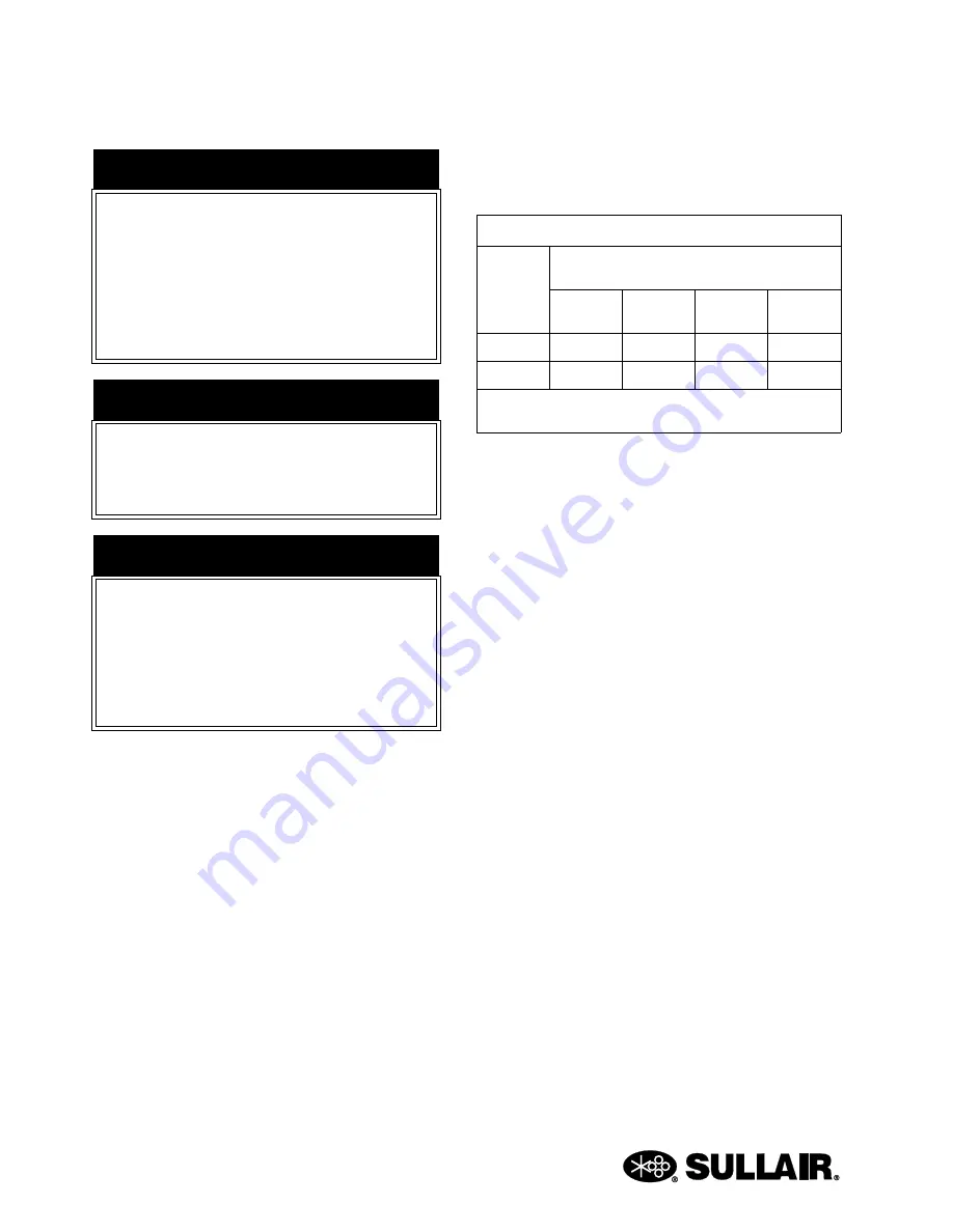
Table 4-1: Water Flow Requirements
Water
Temp °F/
°C
Water Flow
Gallons Per Minute /Liters Per Minute (I)
200HP/
150KW
250HP/
187KW
300HP/
225KW
350HP/
260KW
70/21
36/136
43/163
52/196
61/231
80/27
45/170
54/204
65/246
76/288
(I)
Water pressure should be maintained between 25 and 75
psig (1.7 and 5.2 bar), but not to exceed 145 psig (10 bar).
Содержание TS32 AC
Страница 10: ...NOTES 10...
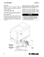
Страница 12: ...TS32 USER MANUAL SECTION 2 12 Figure 2 1 Sullair Series TS32 Rotary Screw Compressor Air cooled Typical...
Страница 13: ...SECTION 2 TS32 USER MANUAL 13 Figure 2 2 Sullair Series TS32 Rotary Screw Compressor Water cooled Typical...
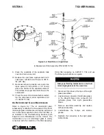
Страница 15: ...SECTION 2 TS32 USER MANUAL 15 Figure 2 3 Compressor Piping and Instrument Diagram Typical...
Страница 16: ...TS32 USER MANUAL SECTION 2 16 Figure 2 4 Compressor Cooling and Lubrication System Air cooled...
Страница 17: ...SECTION 2 TS32 USER MANUAL 17 Figure 2 5 Compressor Cooling and Lubrication System Water cooled...
Страница 18: ...TS32 USER MANUAL SECTION 2 18 Figure 2 6 Compressor Discharge System Air cooled 200 350HP...
Страница 19: ...SECTION 2 TS32 USER MANUAL 19 Figure 2 7 Compressor Discharge System Water cooled 200 350HP...
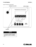
Страница 20: ...TS32 USER MANUAL SECTION 2 20 Figure 2 8 Control System START Typical...
Страница 21: ...SECTION 2 TS32 USER MANUAL 21 Figure 2 9 Control System MODULATION Typical...
Страница 22: ...TS32 USER MANUAL SECTION 2 22 Figure 2 10 Control System UNLOAD Typical...
Страница 23: ...SECTION 2 TS32 USER MANUAL 23 Figure 2 11 Control System FULL LOAD Typical...
Страница 26: ...TS32 USER MANUAL SECTION 2 26 Figure 2 12 Compressor Air Inlet System...
Страница 30: ...TS32 USER MANUAL SECTION 3 30 Figure 3 2 Identification Air Cooled 02250126 376 R02...
Страница 32: ...TS32 USER MANUAL SECTION 3 32 Figure 3 2 Identification Water Cooled 02250126 378 R03...
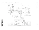
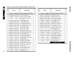
Страница 34: ...TS32 USER MANUAL SECTION 3 34 Figure 3 3 Piping and Instrumentation Diagram Air Cooled 02250179 499 R01...
Страница 38: ...TS32 USER MANUAL SECTION 3 38 Figure 3 5 Piping and Instrumentation Diagram Remote Air Cooled 02250179 498 R01...
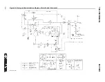
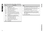
Страница 42: ...TS32 USER MANUAL SECTION 3 42 Figure 3 6 Piping and Instrumentation Diagram Water Cooled 02250179 496 R01...
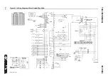
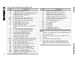
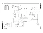
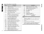
Страница 46: ...TS32 USER MANUAL SECTION 3 46 Figure 3 7 Wiring Diagram Water Cooled Wye Delta 02250178 841 R01...
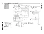
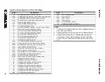
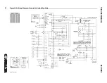
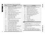
Страница 48: ...TS32 USER MANUAL SECTION 3 48 Figure 3 8 Wiring Diagram Air Cooled Full Voltage 02250178 845 R01...
Страница 50: ...TS32 USER MANUAL SECTION 3 50 Figure 3 9 Wiring Diagram Air Cooled SSRV 02250178 844 R03...
Страница 52: ...TS32 USER MANUAL SECTION 3 52 Figure 3 10 Wiring Diagram Remote Air Cooled Wye Delta 02250178 836 R01...
Страница 54: ...NOTES 54...
Страница 78: ...NOTES 78...
Страница 79: ...NOTES 79...


