Section 4
55
TS32 USER MANUAL
INSTALLATION
4.1
COMPRESSOR
MOUNTING— SUPPORT
AND LOCATION
A foundation or mounting capable of supporting the
weight of the compressor, and rigid enough to
maintain the compressor frame level and the
compressor in alignment is required. The
compressor frame must be leveled and secured with
foundation bolts, and full uniform contact must be
maintained between the frame and foundation. It is
recommended that the frame be grouted to the
foundation. The compressor unit and driver must be
aligned after installation as specified in the
Operator’s Manual. No piping loads shall be
transmitted to the compressor or the cooling package
at the external connections.
• Use flex connectors to prevent piping loads
from being transmitted to the compressor.
• National and local electrical codes specify-
ing the required clearances for the area
around the electrical panel must be com-
plied with.
• Ensure the lighting at the compressor’s
location is sufficient for safe operation and
maintenance.
• The compressor’s location should be one
that allows access for maintenance vehi-
cles and lifting equipment.
• The clearances around the compressor
should permit easy access to all compres-
sor components.
• Walls and ceilings with soft or porous sur-
faces absorb sound and reduce ambient
noise levels. Hard surfaces reflect noise
and have little effect on ambient noise lev-
els.
• Water-cooled compressors must be located
where a cooling water supply and drainage
are available.
4.2
VENTILATION AND
COOLING
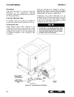
A
IR
-C
OOLED
C
OMPRESSORS
• Air-cooled compressors require a three foot
(one meter) clearance around their perime-
ter.
• The location should be free from standing
water.
• Clean air should be supplied to the com-
pressor, free from exhaust and paint
fumes, dust, metal particles, or caustic
chemical vapors.
• Hot exhaust air should be vented out of the
area to prevent its recirculation back into
the compressor’s cooling system.
• Ducting or some other means must be
used to ensure that hot exhaust air is
vented away from the compressor if the
compressor’s housing has minimal over-
head clearance.
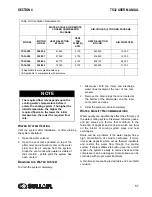
NOTE
When the compressor will be exposed to
temperatures lower than 32°F(0°C) the
cold weather option for freeze protection
must be installed. Consult Sullair Cus-
tomer Care regarding operation on sub-
freezing temperatures.
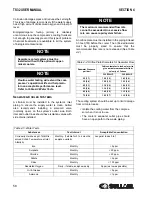
NOTE
Compressors operated in environments
where ambient temperatures average
above 104°F(40°C) must be equipped with
the high-ambient option.
Содержание TS32 AC
Страница 10: ...NOTES 10...
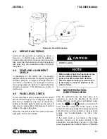
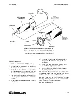
Страница 12: ...TS32 USER MANUAL SECTION 2 12 Figure 2 1 Sullair Series TS32 Rotary Screw Compressor Air cooled Typical...
Страница 13: ...SECTION 2 TS32 USER MANUAL 13 Figure 2 2 Sullair Series TS32 Rotary Screw Compressor Water cooled Typical...
Страница 15: ...SECTION 2 TS32 USER MANUAL 15 Figure 2 3 Compressor Piping and Instrument Diagram Typical...
Страница 16: ...TS32 USER MANUAL SECTION 2 16 Figure 2 4 Compressor Cooling and Lubrication System Air cooled...
Страница 17: ...SECTION 2 TS32 USER MANUAL 17 Figure 2 5 Compressor Cooling and Lubrication System Water cooled...
Страница 18: ...TS32 USER MANUAL SECTION 2 18 Figure 2 6 Compressor Discharge System Air cooled 200 350HP...
Страница 19: ...SECTION 2 TS32 USER MANUAL 19 Figure 2 7 Compressor Discharge System Water cooled 200 350HP...
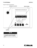
Страница 20: ...TS32 USER MANUAL SECTION 2 20 Figure 2 8 Control System START Typical...
Страница 21: ...SECTION 2 TS32 USER MANUAL 21 Figure 2 9 Control System MODULATION Typical...
Страница 22: ...TS32 USER MANUAL SECTION 2 22 Figure 2 10 Control System UNLOAD Typical...
Страница 23: ...SECTION 2 TS32 USER MANUAL 23 Figure 2 11 Control System FULL LOAD Typical...
Страница 26: ...TS32 USER MANUAL SECTION 2 26 Figure 2 12 Compressor Air Inlet System...
Страница 30: ...TS32 USER MANUAL SECTION 3 30 Figure 3 2 Identification Air Cooled 02250126 376 R02...
Страница 32: ...TS32 USER MANUAL SECTION 3 32 Figure 3 2 Identification Water Cooled 02250126 378 R03...
Страница 34: ...TS32 USER MANUAL SECTION 3 34 Figure 3 3 Piping and Instrumentation Diagram Air Cooled 02250179 499 R01...
Страница 38: ...TS32 USER MANUAL SECTION 3 38 Figure 3 5 Piping and Instrumentation Diagram Remote Air Cooled 02250179 498 R01...
Страница 42: ...TS32 USER MANUAL SECTION 3 42 Figure 3 6 Piping and Instrumentation Diagram Water Cooled 02250179 496 R01...
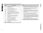
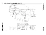
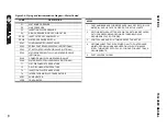
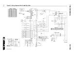
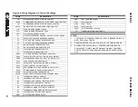
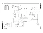
Страница 46: ...TS32 USER MANUAL SECTION 3 46 Figure 3 7 Wiring Diagram Water Cooled Wye Delta 02250178 841 R01...
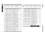
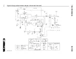
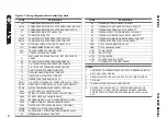
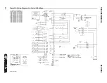
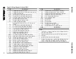
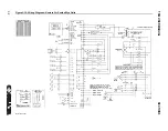
Страница 48: ...TS32 USER MANUAL SECTION 3 48 Figure 3 8 Wiring Diagram Air Cooled Full Voltage 02250178 845 R01...
Страница 50: ...TS32 USER MANUAL SECTION 3 50 Figure 3 9 Wiring Diagram Air Cooled SSRV 02250178 844 R03...
Страница 52: ...TS32 USER MANUAL SECTION 3 52 Figure 3 10 Wiring Diagram Remote Air Cooled Wye Delta 02250178 836 R01...
Страница 54: ...NOTES 54...
Страница 78: ...NOTES 78...
Страница 79: ...NOTES 79...


