TS32 USER MANUAL
SECTION 4
58
Corrosion damages pipes and reduces their strength.
This type of damage is more likely if the water supply
has a high amount of dissolved oxygen and a low pH
level.
Biological/organic fouling (slime) is relatively
uncommon since the compressor’s cooling fluids are
hot enough to generally prevent this type of problem.
Chemical treatments are available to rid the system
of biological contaminants.
S
EAWATER
-C
OOLED
S
YSTEMS
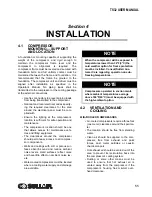
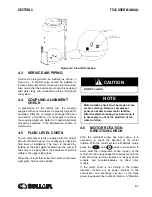
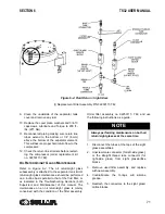
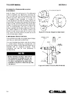
A strainer must be installed in the system’s inlet
piping to ensure the supply water is clean. Sullair
also recommends installing a solenoid valve
(normally open) on the system’s outlet side. Both
inlet and outlet lines should have isolation valves with
side drains installed.
An orifice plate must be installed in the piping at least
3.3 feet (1M) before the cooler. The orifice’s diameter
must be properly sized to ensure that the
recommended flow rate is not exceeded (See
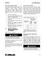
The cooling system should be set up to limit damage
from oil cooler leaks:
• Isolate the cooling water from the compres-
sor when it is not in use.
• The cooler’s seawater outlet pipe should
have an open path to the waste piping.
NOTE
Seawater-cooled systems must be
installed with with the optional copper-
nickel coolers.
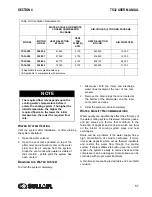
NOTE
Routine water testing will extend the com-
pressor’s operational life and help main-
tain an acceptable performance level.
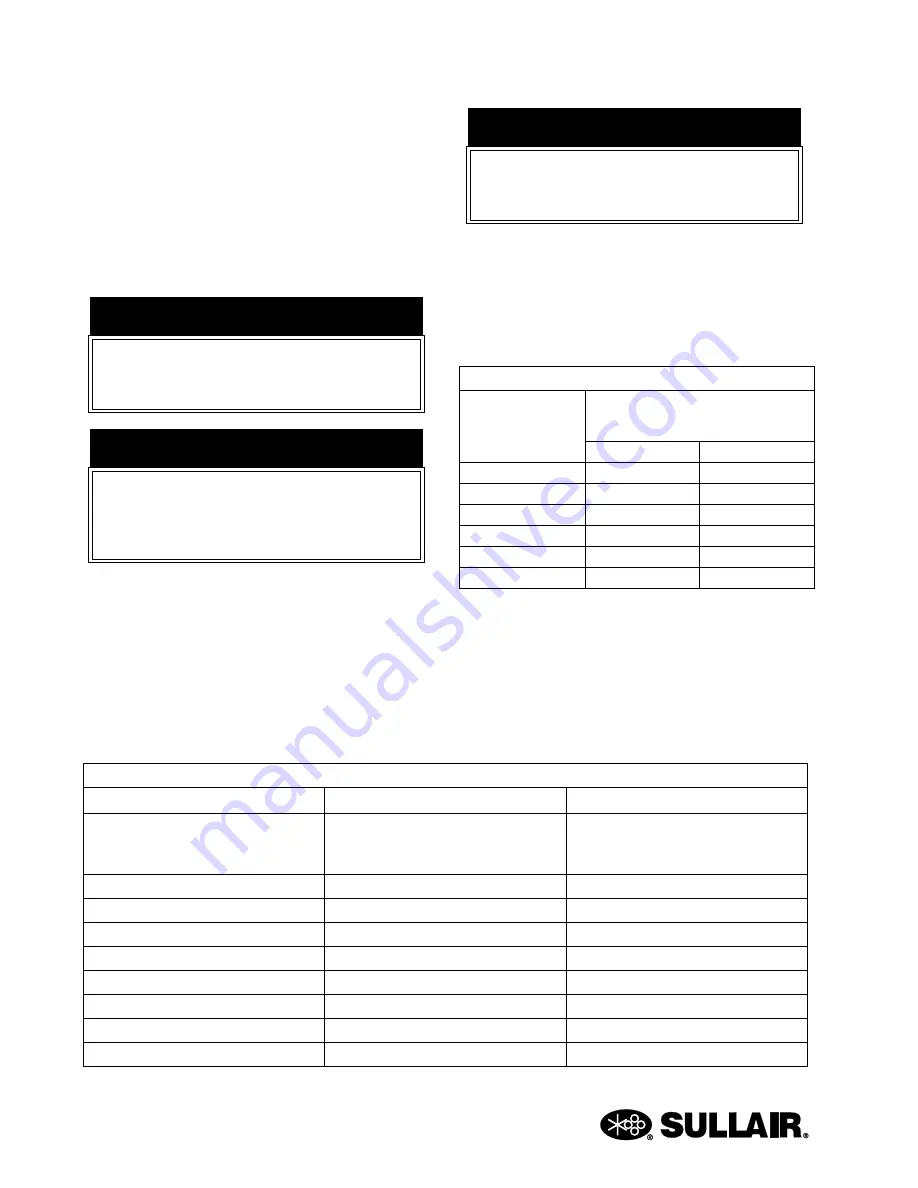
Refer to
Table 4-3: Water Tests
Substances
Test Interval
Acceptable Concentration
Corrosivity Hardness, pH, Total Dis-
solved Solids, Temperature at inlet,
Alkalinity
Monthly - if stable for 3 to 4 months,
analyze quarterly.
Langelier Index 0 to 1
Iron
Monthly
< 2 ppm
Sulphate
Monthly
< 50 ppm
Chloride
Monthly
< 50 ppm
Nitrate
Monthly
< 2 ppm
Silica
Monthly
< 100 ppm
Desolated Oxygen
Daily - if stable, analyze weekly
0 ppm (as low as possible)
Oil & Grease
Monthly
< 5 ppm
Ammonia
Monthly
< 1 ppm
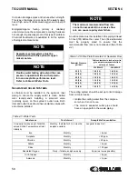
NOTE
The maximum recommended flow rate
cannot be exceeded. An excessive flow
rate can cause rapid system failure.
Table 4-4: Orifice Plate Diameters for Seawater Flow
Seawater Pressure
psi (bar)
Orifice diameter in inches (mm) to
give a maximum seawater flow
velocity of 3m/sec
200/250HP
300/350HP
25 (1.7)
1.38 (35)
1.43 (36)
35 (2.4)
1.28 (33)
1.33 (34)
45 (3.1)
1.19 (30)
1.24 (32)
55 (3.8)
1.14 (29)
1.19 (30)
65 (4.5)
1.09 (28)
1.13 (29)
75 (5.2)
1.05 (27)
1.10 (28)
Содержание TS32 AC
Страница 10: ...NOTES 10...
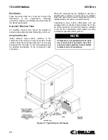
Страница 12: ...TS32 USER MANUAL SECTION 2 12 Figure 2 1 Sullair Series TS32 Rotary Screw Compressor Air cooled Typical...
Страница 13: ...SECTION 2 TS32 USER MANUAL 13 Figure 2 2 Sullair Series TS32 Rotary Screw Compressor Water cooled Typical...
Страница 15: ...SECTION 2 TS32 USER MANUAL 15 Figure 2 3 Compressor Piping and Instrument Diagram Typical...
Страница 16: ...TS32 USER MANUAL SECTION 2 16 Figure 2 4 Compressor Cooling and Lubrication System Air cooled...
Страница 17: ...SECTION 2 TS32 USER MANUAL 17 Figure 2 5 Compressor Cooling and Lubrication System Water cooled...
Страница 18: ...TS32 USER MANUAL SECTION 2 18 Figure 2 6 Compressor Discharge System Air cooled 200 350HP...
Страница 19: ...SECTION 2 TS32 USER MANUAL 19 Figure 2 7 Compressor Discharge System Water cooled 200 350HP...
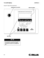
Страница 20: ...TS32 USER MANUAL SECTION 2 20 Figure 2 8 Control System START Typical...
Страница 21: ...SECTION 2 TS32 USER MANUAL 21 Figure 2 9 Control System MODULATION Typical...
Страница 22: ...TS32 USER MANUAL SECTION 2 22 Figure 2 10 Control System UNLOAD Typical...
Страница 23: ...SECTION 2 TS32 USER MANUAL 23 Figure 2 11 Control System FULL LOAD Typical...
Страница 26: ...TS32 USER MANUAL SECTION 2 26 Figure 2 12 Compressor Air Inlet System...
Страница 30: ...TS32 USER MANUAL SECTION 3 30 Figure 3 2 Identification Air Cooled 02250126 376 R02...
Страница 32: ...TS32 USER MANUAL SECTION 3 32 Figure 3 2 Identification Water Cooled 02250126 378 R03...
Страница 34: ...TS32 USER MANUAL SECTION 3 34 Figure 3 3 Piping and Instrumentation Diagram Air Cooled 02250179 499 R01...
Страница 38: ...TS32 USER MANUAL SECTION 3 38 Figure 3 5 Piping and Instrumentation Diagram Remote Air Cooled 02250179 498 R01...
Страница 42: ...TS32 USER MANUAL SECTION 3 42 Figure 3 6 Piping and Instrumentation Diagram Water Cooled 02250179 496 R01...
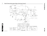
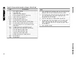
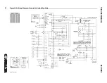
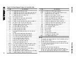
Страница 46: ...TS32 USER MANUAL SECTION 3 46 Figure 3 7 Wiring Diagram Water Cooled Wye Delta 02250178 841 R01...
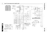
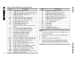
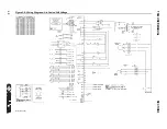
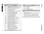
Страница 48: ...TS32 USER MANUAL SECTION 3 48 Figure 3 8 Wiring Diagram Air Cooled Full Voltage 02250178 845 R01...
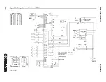
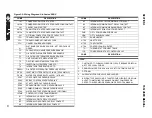
Страница 50: ...TS32 USER MANUAL SECTION 3 50 Figure 3 9 Wiring Diagram Air Cooled SSRV 02250178 844 R03...
Страница 52: ...TS32 USER MANUAL SECTION 3 52 Figure 3 10 Wiring Diagram Remote Air Cooled Wye Delta 02250178 836 R01...
Страница 54: ...NOTES 54...
Страница 78: ...NOTES 78...
Страница 79: ...NOTES 79...


