
TS32 USER MANUAL
SECTION 2
14
After the air/fluid mixture is discharged from the
compressor unit, the fluid is separated from the air.
At this time, the air flows to the service line and the
fluid is cooled in preparation for re-injection.
The fluid also serves as lubricant for the anti-friction
bearings and the drive gear sets.
2.3
COMPRESSOR COOLING
AND LUBRICATION
SYSTEM, FUNCTIONAL
DESCRIPTION
through
. The cooling
and lubrication system (air-cooled version) consists
of a fan, radiator-type cooler/aftercooler assembly,
full-flow main line filter, thermal valve and
interconnecting piping.
For the water-cooled models, a shell and tube fluid
cooler, and aftercooler are substituted for the
radiator- type cooler on air-cooled compressors. The
pressure in the separator/sump tank causes fluid
flow by forcing the fluid from the high pressure area
of the sump to an area of lower pressure in the
compressor unit.
Fluid flows from the bottom of the separator/sump
tank to the thermal valve. The thermal valve is fully
open to the compressor unit when the fluid
temperature is below 185ºF (85ºC). The fluid passes
through the thermal valve, the main filter and directly
to the compressor unit where it lubricates, cools and
seals the rotors and the compression chamber.
As the discharge temperature rises above 185ºF
(85ºC), due to the heat of compression, the thermal
valve begins to close and a portion of the fluid then
flows through the cooler. From the cooler, the fluid
flows to the main filter and on to the compressor unit.
The filter has a replacement element and an integral
pressure bypass valve. When the element pressure
exceeds 20 psid (1.4 bar), the filter begins to bypass.
The Supervisor monitors the filter pressure drop and
displays a maintenance requirement message.
A fluid stop valve is also present in the lubrication
circuit. The fluid stop valve prevents fluid from filling
the compressor unit when the compressor is shut
down. When the compressor is operating, the fluid
stop valve is held open by air pressure from the
compressor unit allowing a free flow of fluid from the
separator/sump tank back to the compressor unit. On
shutdown, the compressor unit pressure is reduced,
causing the fluid stop valve to close and isolate the
compressor unit from the cooling system.
Water-cooled models have a water pressure switch
to prevent operation with inadequate water pressure.
2.4
COMPRESSOR DISCHARGE
SYSTEM, FUNCTIONAL
DESCRIPTION
,
and
. The
compressor unit discharges the compressed air/fluid
mixture into the combination separator/sump tank.
The separator/sump tank has three functions:
• It acts as a primary fluid separator.
• Serves as the compressor fluid sump.
• Houses the final fluid separator elements.
The compressed air/fluid mixture enters the
separator/sump tank and is directed through a
centrifugal baffle. Through centrifugal action and a
velocity reduction large droplets of fluid form and fall
to the bottom of the separator/sump tank. The
fractional percentage of fluid remaining in the
compressed air collects on the surface of the dual
separator elements as the compressed air flows
through them. Two return lines (or scavenge tubes)
lead from the bottom of each separator element to
the low pressure region of the compressor unit. Fluid
collecting on the bottom of each separator is returned
to the compressor by a pressure difference between
the separator/sump tank and the compressor inlet.
Sight glasses are located in the return lines to
observe this fluid flow. There are also orifices
(protected by strainers) within the sight glasses to
assure proper flow. When the total pressure drop
across the elements exceeds 10 psid (0.7 bar), the
Supervisor displays a maintenance requirement
message.
The separator/sump tank is a pressure vessel
designed and built to codes administered by
appropriate governing bodies. A combination
minimum pressure/check valve, located downstream
from the separator, assures a minimum separator/
sump tank pressure of 50 psig (3.5 bar) during all
conditions. This pressure is necessary for proper air/
fluid separation and proper fluid circulation while
supplying air to the system. This valve also acts as a
check valve preventing compressed air in the service
line from bleeding back into the separator/sump tank
on shutdown and during operation on the
compressor in an unloaded condition.
NOTE
Standard thermal valve temperature is
175ºF/79ºC (operating temperature of 180ºF/
82ºC). Thermal valve temperature is 190ºF/
88ºC (operating temperature of 195ºF/ 91ºC)
for HH, XH and 24KT machines.
Содержание TS32 AC
Страница 10: ...NOTES 10...
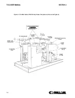
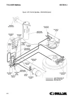
Страница 12: ...TS32 USER MANUAL SECTION 2 12 Figure 2 1 Sullair Series TS32 Rotary Screw Compressor Air cooled Typical...
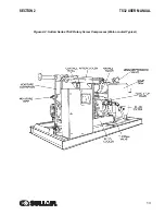
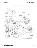
Страница 13: ...SECTION 2 TS32 USER MANUAL 13 Figure 2 2 Sullair Series TS32 Rotary Screw Compressor Water cooled Typical...
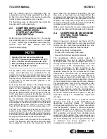
Страница 15: ...SECTION 2 TS32 USER MANUAL 15 Figure 2 3 Compressor Piping and Instrument Diagram Typical...
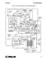
Страница 16: ...TS32 USER MANUAL SECTION 2 16 Figure 2 4 Compressor Cooling and Lubrication System Air cooled...
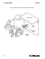
Страница 17: ...SECTION 2 TS32 USER MANUAL 17 Figure 2 5 Compressor Cooling and Lubrication System Water cooled...
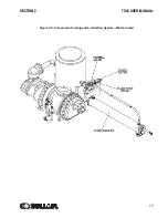
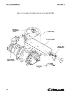
Страница 18: ...TS32 USER MANUAL SECTION 2 18 Figure 2 6 Compressor Discharge System Air cooled 200 350HP...
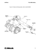
Страница 19: ...SECTION 2 TS32 USER MANUAL 19 Figure 2 7 Compressor Discharge System Water cooled 200 350HP...
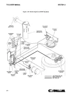
Страница 20: ...TS32 USER MANUAL SECTION 2 20 Figure 2 8 Control System START Typical...
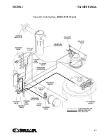
Страница 21: ...SECTION 2 TS32 USER MANUAL 21 Figure 2 9 Control System MODULATION Typical...
Страница 22: ...TS32 USER MANUAL SECTION 2 22 Figure 2 10 Control System UNLOAD Typical...
Страница 23: ...SECTION 2 TS32 USER MANUAL 23 Figure 2 11 Control System FULL LOAD Typical...
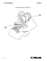
Страница 26: ...TS32 USER MANUAL SECTION 2 26 Figure 2 12 Compressor Air Inlet System...
Страница 30: ...TS32 USER MANUAL SECTION 3 30 Figure 3 2 Identification Air Cooled 02250126 376 R02...
Страница 32: ...TS32 USER MANUAL SECTION 3 32 Figure 3 2 Identification Water Cooled 02250126 378 R03...
Страница 34: ...TS32 USER MANUAL SECTION 3 34 Figure 3 3 Piping and Instrumentation Diagram Air Cooled 02250179 499 R01...
Страница 38: ...TS32 USER MANUAL SECTION 3 38 Figure 3 5 Piping and Instrumentation Diagram Remote Air Cooled 02250179 498 R01...
Страница 42: ...TS32 USER MANUAL SECTION 3 42 Figure 3 6 Piping and Instrumentation Diagram Water Cooled 02250179 496 R01...
Страница 46: ...TS32 USER MANUAL SECTION 3 46 Figure 3 7 Wiring Diagram Water Cooled Wye Delta 02250178 841 R01...
Страница 48: ...TS32 USER MANUAL SECTION 3 48 Figure 3 8 Wiring Diagram Air Cooled Full Voltage 02250178 845 R01...
Страница 50: ...TS32 USER MANUAL SECTION 3 50 Figure 3 9 Wiring Diagram Air Cooled SSRV 02250178 844 R03...
Страница 52: ...TS32 USER MANUAL SECTION 3 52 Figure 3 10 Wiring Diagram Remote Air Cooled Wye Delta 02250178 836 R01...
Страница 54: ...NOTES 54...
Страница 78: ...NOTES 78...
Страница 79: ...NOTES 79...


