SECTION 6
TS32 USER MANUAL
73
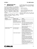
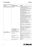
S
HAFT
C
OUPLING
M
AINTENANCE
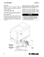
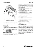
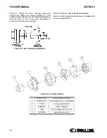
The compressor unit and motor are rigidly connected
through the mounting adapter housing. This
arrangement makes coupling alignment
unnecessary. The coupling is a jaw type in shear. If
the elastomeric (rubber) element requires
replacement due to wear or damage, order a
replacement element and perform the following
steps:
1. Remove the coupling guard.
2. Loosen the retaining screw located on the
outer sleeve. Slide the sleeve to one side,
exposing the coupling element.
3. Unwrap the coupling element from the
coupling jaws.
4. Position the motor and compressor keyways
180 degrees apart
5. Install the new element by wrapping it
around the jaws, engaging the cogs on the
element into the jaws.
6. Reinstall the outer sleeve and secure by
tightening the two screws to 45 in·lbs (5 Nm).
7. Reinstall the coupling guard.
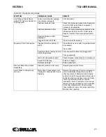
6.7
DRIVE COUPLING
INSTALLATION AND
ALIGNMENT
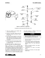
Refer to
.
For installation and alignment of the drive coupling,
follow the steps explained below.
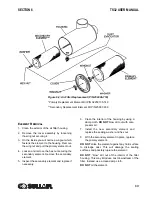
STEP 1 MOUNT HUBS
Mount the motor hub and the compressor hub onto
respective shaft. Position the hubs to establish the
correct gap specified in
. Secure each hub
with a setscrew.
STEP 2 OFFSET ALIGNMENT
Clean any oil, grease, dirt or paint from coupling
faces and the other surfaces of the drive flanges.
Rotate shafts so that a straight edge will rest
squarely (or within the 0.010 inch maximum limit
shown in
) on both flanges and at a point
90° away. The vertical offset alignment is adjusted by
the addition or removal of motor mounting shims.
Loosen the motor mounting bolts and slide the motor
sideways to correct the horizontal offset.
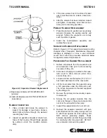
STEP 3 COUPLING GAP AND ANGULAR
ALIGNMENT
Position the hubs to establish the proper gap and
angular alignment as indicated in
determine the angular misalignment in inches,
measure the maximum space between the hub
flanges and the minimum space 180° away, and then
subtract. To adjust the horizontal angular
misalignment, loosen the motor mounting bolts and
adjust the motor position until the angular alignment
is within tolerance.When within the limits specified in
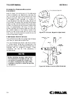
WARNING
Disconnect all power at source, before
attempting maintenance or adjustments.
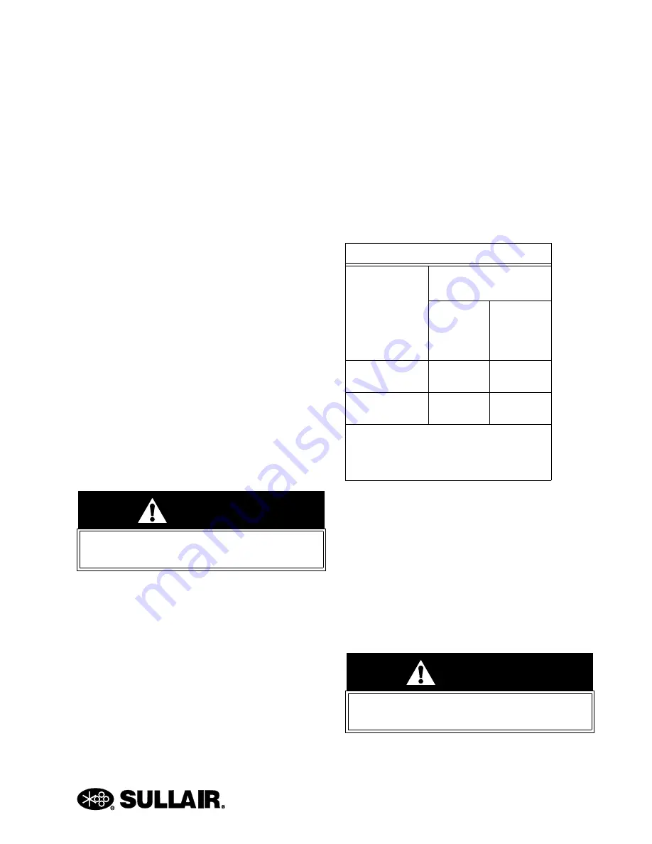
Table 6-1: INSTALLATION DATA
Coupling Gap
inches/mm
Max. Operating
Misalignment
Parallel
Offset
inches/
mm
Angular
inches/
mm (I)
.188
+/- .020 in.
.010 in.
.010 in.
4.77
+/- .50 mm
.25 mm
.25 mm
(I)
Angular misalignment in inches equals
maximum A minus minimum B as shown in
. DO NOT exceed values in Table
above.
WARNING
Disconnect all power at source, before
attempting maintenance or adjustments.
Содержание TS32 AC
Страница 10: ...NOTES 10...
Страница 12: ...TS32 USER MANUAL SECTION 2 12 Figure 2 1 Sullair Series TS32 Rotary Screw Compressor Air cooled Typical...
Страница 13: ...SECTION 2 TS32 USER MANUAL 13 Figure 2 2 Sullair Series TS32 Rotary Screw Compressor Water cooled Typical...
Страница 15: ...SECTION 2 TS32 USER MANUAL 15 Figure 2 3 Compressor Piping and Instrument Diagram Typical...
Страница 16: ...TS32 USER MANUAL SECTION 2 16 Figure 2 4 Compressor Cooling and Lubrication System Air cooled...
Страница 17: ...SECTION 2 TS32 USER MANUAL 17 Figure 2 5 Compressor Cooling and Lubrication System Water cooled...
Страница 18: ...TS32 USER MANUAL SECTION 2 18 Figure 2 6 Compressor Discharge System Air cooled 200 350HP...
Страница 19: ...SECTION 2 TS32 USER MANUAL 19 Figure 2 7 Compressor Discharge System Water cooled 200 350HP...
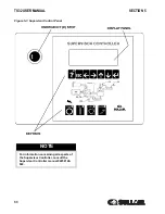
Страница 20: ...TS32 USER MANUAL SECTION 2 20 Figure 2 8 Control System START Typical...
Страница 21: ...SECTION 2 TS32 USER MANUAL 21 Figure 2 9 Control System MODULATION Typical...
Страница 22: ...TS32 USER MANUAL SECTION 2 22 Figure 2 10 Control System UNLOAD Typical...
Страница 23: ...SECTION 2 TS32 USER MANUAL 23 Figure 2 11 Control System FULL LOAD Typical...
Страница 26: ...TS32 USER MANUAL SECTION 2 26 Figure 2 12 Compressor Air Inlet System...
Страница 30: ...TS32 USER MANUAL SECTION 3 30 Figure 3 2 Identification Air Cooled 02250126 376 R02...
Страница 32: ...TS32 USER MANUAL SECTION 3 32 Figure 3 2 Identification Water Cooled 02250126 378 R03...
Страница 34: ...TS32 USER MANUAL SECTION 3 34 Figure 3 3 Piping and Instrumentation Diagram Air Cooled 02250179 499 R01...
Страница 38: ...TS32 USER MANUAL SECTION 3 38 Figure 3 5 Piping and Instrumentation Diagram Remote Air Cooled 02250179 498 R01...
Страница 42: ...TS32 USER MANUAL SECTION 3 42 Figure 3 6 Piping and Instrumentation Diagram Water Cooled 02250179 496 R01...
Страница 46: ...TS32 USER MANUAL SECTION 3 46 Figure 3 7 Wiring Diagram Water Cooled Wye Delta 02250178 841 R01...
Страница 48: ...TS32 USER MANUAL SECTION 3 48 Figure 3 8 Wiring Diagram Air Cooled Full Voltage 02250178 845 R01...
Страница 50: ...TS32 USER MANUAL SECTION 3 50 Figure 3 9 Wiring Diagram Air Cooled SSRV 02250178 844 R03...
Страница 52: ...TS32 USER MANUAL SECTION 3 52 Figure 3 10 Wiring Diagram Remote Air Cooled Wye Delta 02250178 836 R01...
Страница 54: ...NOTES 54...
Страница 78: ...NOTES 78...
Страница 79: ...NOTES 79...


