
Section 5
63
TS32 USER MANUAL
OPERATION
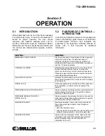
5.1
INTRODUCTION
While Sullair has built into the TS32 Series package
a comprehensive array of controls and indicators to
assure its proper operation, the user should
recognize and interpret readings which call for
service or indicate the onset of a malfunction. Before
starting the unit, the user should become familiar with
the controls and indicators-their purpose, location,
and use.
5.2
PURPOSE OF CONTROLS—
INTRODUCTION
Indicators and functions included in the package are
listed in the following guide. However, all Supervisor
Controller-related functions and indicators are
presented in the Supervisor Controller Manual, so
please refer to that document for additional
information.
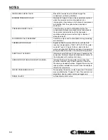
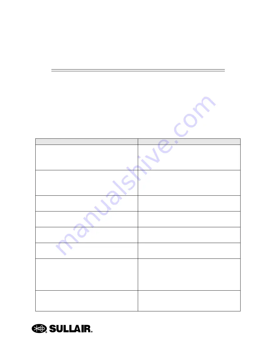
CONTROL:
PURPOSE:
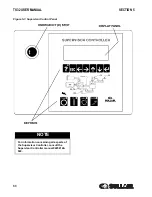
EMERGENCY STOP SWITCH
Pushing in this switch, found adjacent to the Supervisor,
cuts all AC outputs from the Supervisor and de-
energizes the starter. A fault message (E STOP) is
displayed by the Supervisor until the button is pulled out
and the “O” pad is depressed.
THERMAL O/L RESET
Momentarily pushing this button, found on the starter’s
thermal overload element housing, re-closes the
starter’s contacts after a current overload takes place.
Please be aware that the elements must be allowed to
cool sufficiently before resetting.
SULLICON ACTUATOR
Actuates the inlet butterfly valve which throttles the air
flow to the compressor inlet, in order to match air supply
to the demand.
SPIRAL VALVE
Internally bypasses and controls the air flow capacity of
the compressor, in order to match air supply to the
demand.
PRESSURE REGULATOR (SULLICON)
Opens a pressure line between the sump and inlet valve
piston allowing the inlet valve to regulate air delivery
according to the air demand.
PRESSURE REGULATOR (WITH
SPIRAL VALVE)
Opens a pressure line between the service line and the
spiral valve actuator allowing the spiral valve to regulate
air delivery according to air demand.
SOLENOID VALVE #1
Electrically actuated, 3-way valve which controls the
flow of pneumatic logic signals. Used throughout
package to:
• Open the blowdown valve.
• Load the Sullicon device/close the inlet butterfly valve
during shutdown operation. ·Open the spiral valve.
SOLENOID VALVE #2
Opens when the compressor starts; closes when the
compressor is shut off. This prevents any air system
loss and depressurizes the controls when the
compressor is shut off.
Содержание TS32 AC
Страница 10: ...NOTES 10...
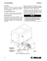
Страница 12: ...TS32 USER MANUAL SECTION 2 12 Figure 2 1 Sullair Series TS32 Rotary Screw Compressor Air cooled Typical...
Страница 13: ...SECTION 2 TS32 USER MANUAL 13 Figure 2 2 Sullair Series TS32 Rotary Screw Compressor Water cooled Typical...
Страница 15: ...SECTION 2 TS32 USER MANUAL 15 Figure 2 3 Compressor Piping and Instrument Diagram Typical...
Страница 16: ...TS32 USER MANUAL SECTION 2 16 Figure 2 4 Compressor Cooling and Lubrication System Air cooled...
Страница 17: ...SECTION 2 TS32 USER MANUAL 17 Figure 2 5 Compressor Cooling and Lubrication System Water cooled...
Страница 18: ...TS32 USER MANUAL SECTION 2 18 Figure 2 6 Compressor Discharge System Air cooled 200 350HP...
Страница 19: ...SECTION 2 TS32 USER MANUAL 19 Figure 2 7 Compressor Discharge System Water cooled 200 350HP...
Страница 20: ...TS32 USER MANUAL SECTION 2 20 Figure 2 8 Control System START Typical...
Страница 21: ...SECTION 2 TS32 USER MANUAL 21 Figure 2 9 Control System MODULATION Typical...
Страница 22: ...TS32 USER MANUAL SECTION 2 22 Figure 2 10 Control System UNLOAD Typical...
Страница 23: ...SECTION 2 TS32 USER MANUAL 23 Figure 2 11 Control System FULL LOAD Typical...
Страница 26: ...TS32 USER MANUAL SECTION 2 26 Figure 2 12 Compressor Air Inlet System...
Страница 30: ...TS32 USER MANUAL SECTION 3 30 Figure 3 2 Identification Air Cooled 02250126 376 R02...
Страница 32: ...TS32 USER MANUAL SECTION 3 32 Figure 3 2 Identification Water Cooled 02250126 378 R03...
Страница 34: ...TS32 USER MANUAL SECTION 3 34 Figure 3 3 Piping and Instrumentation Diagram Air Cooled 02250179 499 R01...
Страница 38: ...TS32 USER MANUAL SECTION 3 38 Figure 3 5 Piping and Instrumentation Diagram Remote Air Cooled 02250179 498 R01...
Страница 42: ...TS32 USER MANUAL SECTION 3 42 Figure 3 6 Piping and Instrumentation Diagram Water Cooled 02250179 496 R01...
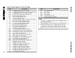
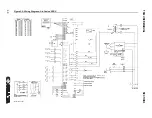
Страница 46: ...TS32 USER MANUAL SECTION 3 46 Figure 3 7 Wiring Diagram Water Cooled Wye Delta 02250178 841 R01...
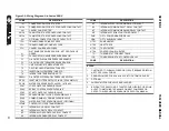
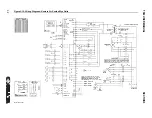
Страница 48: ...TS32 USER MANUAL SECTION 3 48 Figure 3 8 Wiring Diagram Air Cooled Full Voltage 02250178 845 R01...
Страница 50: ...TS32 USER MANUAL SECTION 3 50 Figure 3 9 Wiring Diagram Air Cooled SSRV 02250178 844 R03...
Страница 52: ...TS32 USER MANUAL SECTION 3 52 Figure 3 10 Wiring Diagram Remote Air Cooled Wye Delta 02250178 836 R01...
Страница 54: ...NOTES 54...
Страница 78: ...NOTES 78...
Страница 79: ...NOTES 79...


