b
WARNINGS
The following is compulsory:
•
Use of an omnipolar thermal magnetic circuit breaker, line disconnector, in compliance with EN standards.
•
Observance of the connections L (Phase) - N (Neutral).
•
Use of cable sections of at least 1 mm
2
.
•
Use of an earthing wire that is at least 2 cm longer than those of the L (Phase) - N (Neutral) connections.
•
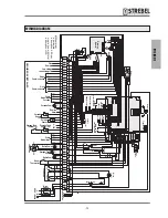
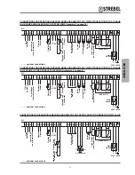
Reference to the wiring diagrams included in this manual for any type of electrical intervention.
•
Connections to an efficient earthing system (*).
•
NEVER use water hoses for earthing the appliance.
•
Great care to observe maximum absorption levels of the external circulation pumps (see "WIRING DIAGRAM" page 15).
(*) The manufacturer declines all liability for any damage caused by failure to earth the appliance or specifications
in the wiring diagrams.
REMOTE ALARM
The outputs of terminals 27-28 supply a voltage-free contact for the management of an alarm signal. This contact is acti-
vated each time an error/malfunction occurs on the heating unit.
b
WARNINGS
•
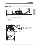
In the event of an error/malfunction of the heating unit the “Block indicator light due to intervention of safety devices”
Sbs, on the control panel, does not light up. This light only illuminates if one of the ISPESL safety devices trips (if
correctly connected as shown in the wiring diagram) at the same time as disconnection of the electrical power supply
to the heating unit.
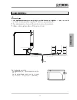
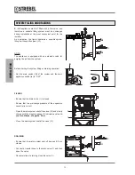
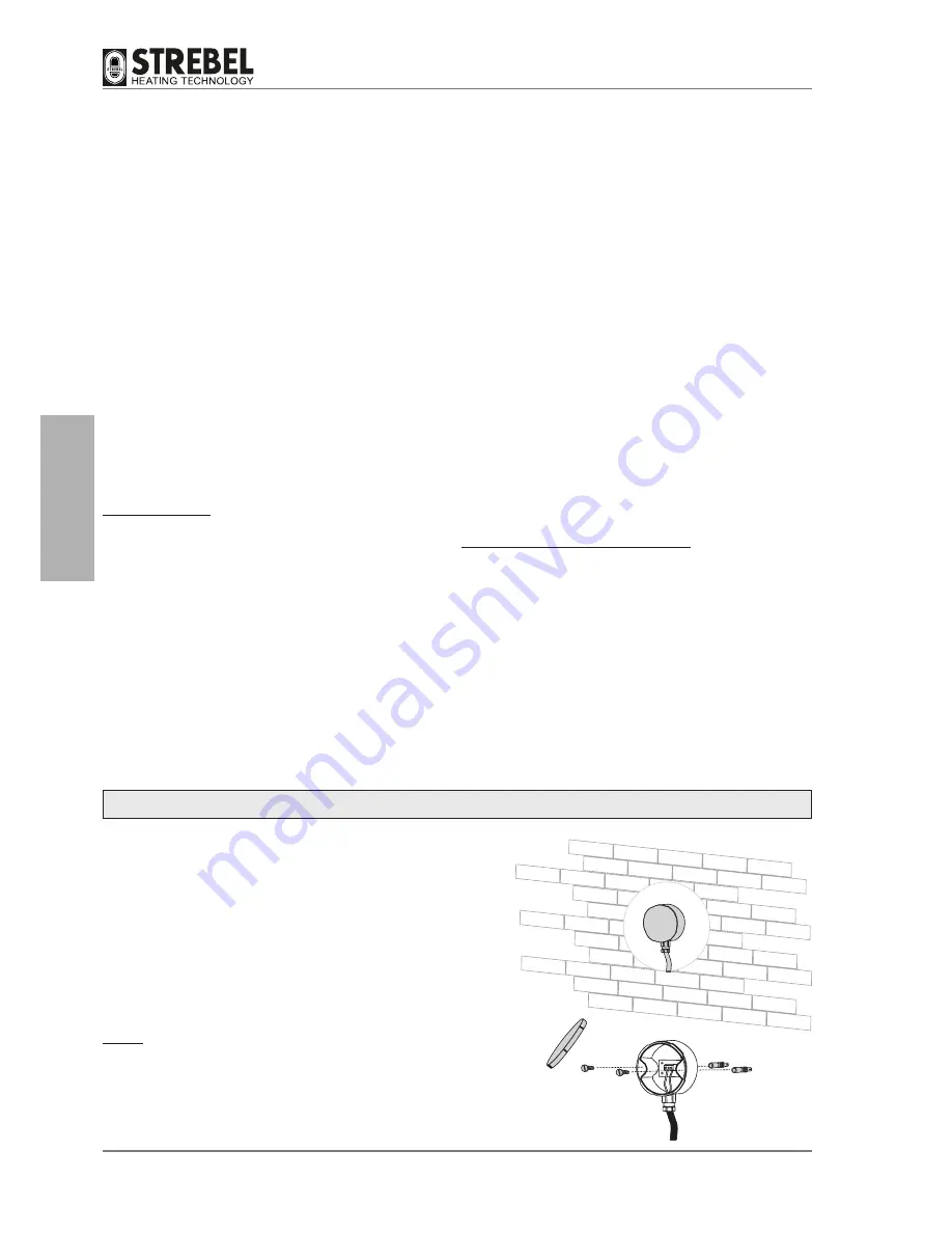
CONNECTION OF OUTSIDE SENSOR (OPTIONAL)
The outside sensor must be installed on the outside of the building,
on a flat surface in a north/north-east position (the coolest side)
and at a safe distance from the flues, doors, windows and areas
exposed to direct sunlight.
To install, proceed as follows:
- Remove the cover.
- Fix the sensor to the wall using two plugs.
- Make the electrical connections.
NOTE:
- Minimum cable section: 1 mm
2
.
- Maximum connection length: 50 m.
- Non-polarised connection terminals.
- Use shielded coaxial cables, with 2 wires and connect the
sheath to earth.
- 24
-
INST
ALLA
TION

