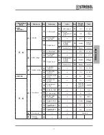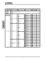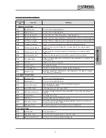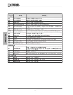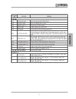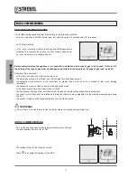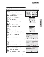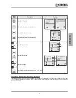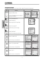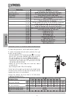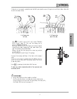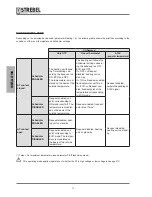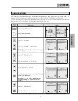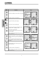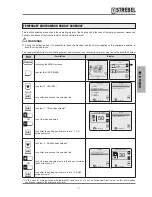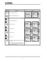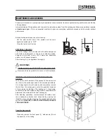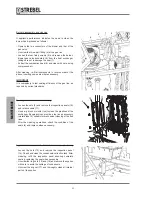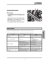
If these do not correspond, gradually adjust the MAX gas adjuster screw on the gas valve until the analyser shows the
correct combustion values.
+
-
+
-
-
+
-
+
S - AF gas valve
115 / 150
Gas
MAX
Gas
MAX
Gas
MIN
Gas
MIN
S - AF gas valve
200 / 240 / 280
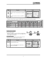
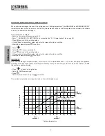
- Press
A
to reduce power to 0% (see section "MANUAL
TEST function" page 47). This sets the heating unit to
operate at Minimum Capacity.
- The blower RPM is shown on the display, at minimum capacity.
Check that this value corresponds to the value stated in the
table “TECHNICAL SPECIFICATIONS”.
- Measure the gas flow rate, taking into account any relevant
corrective factors.
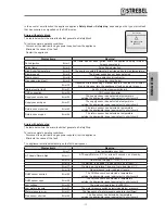
- Use the analyser to take CO
2
and CO readings.
Compare the readings with those of the table on the previous
page.
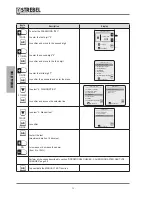
If these do not correspond, gradually adjust the MIN gas adjuster
screw on the gas valve until the analyser shows the correct
combustion values.
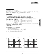
Press
C
to deactivate the MANUAL TEST function.
If necessary, make adjustments both at the maximum and
minimum values.
2D
D
b
WARNINGS
•
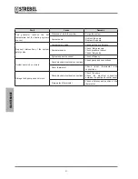
If the control values are not accessible, check that:
- the flue extraction ducts or air intake ducts are not obstructed;
- the gas pressure is not lower than 18 mbar (G20) or 25 mbar (G31);
- the blower RPM is correct (see page 47).
- 51
-
INST
ALLA
TION

