background image

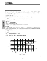
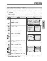
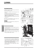
TEMPORARY SHUTDOWN OR HOLIDAY SCHEDULE

This function enables a reduction in the operating regime of the heating unit in the case of temporary absences, weekends, 

holidays and above all automatic restart after the set time interval.

b

 WARNINGS


During the holiday period, it is essential to leave the electrical and gas mains supplies to the appliance powered, to 

ensure correct operation.

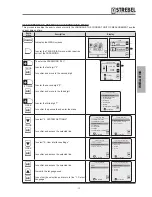
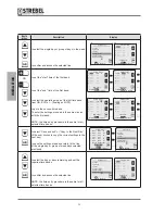
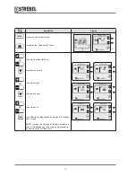
The supply temperatures for the heating system and/or production of domestic hot water, must be set as described below:

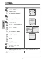
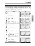
Key to 

press

Description

Display

F

A

to display the MENU screens

to enter the USER MENU

date

OUTSIDE

7

o

C

69

o

0.0

OFF OFF

time


MENU

USER

TECHNICIAN


a

A
A

D

TWICE

C

to select "3. HOLIDAY"

to confirm and access the selected line

oK

User menu

1. HEATING

2. DOMESTIC HOT WATER

3. HOLIDAY

4. MAINTENANCE

5. SETTINGS

6. DIAGNOSTICS

to confirm


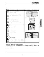
oK

Holiday

1. CH holiday setpoint
2. DHW holiday setpoint

to confirm

C


A

OR


A

C

to select "1. CH holiday setpoint"

to set the required value

to confirm the settings and return to line “1. CH 

holiday setpoint"

CH holiday setpoint

50

oK

to confirm


oK

Holiday

1. CH holiday setpoint
2. DHW holiday setpoint

to confirm

D

C


A

OR


A

C

to select "2. DHW holiday setpoint"

to confirm and access the selected line

to set the required value (only in the case of storage 

tanks with sensor) (*)

to confirm the settings and return to line “2. DHW 

holiday setpoint"

Holiday

1. CH holiday setpoint
2. DHW holiday setpoint

oK

to confirm


DHW holiday setpoint

30

oK

to confirm

(*) In the case of storage tanks with thermostat, take care not to set an excessively low value, as this could cause 

continuous requests for domestic hot water.

- 57 

-

INST

ALLA

TION

Содержание S-AF

Страница 1: ...STREBEL S AF Floor standing high efficiency boiler Installation Maintenance Manual 2015 06 15 v1 0 ...

Страница 2: ...y observed as stated in this manual The S AF appliances comply with the following Gas directive 2009 142 EC Efficiency Directive 92 42 EEC Low voltage directive 2006 95 EC Electromagnetic compatibility directive 2004 108 EC Energy Efficiency Condensing classification NOx Class 5 70 mg kWh For the serial number and year of manufacturer refer to the technical data plate CONFORMITY Company Management...

Страница 3: ...ND EXTRACTION OF COMBUSTION AIR 26 CONDENSATE REMOVAL 29 SYSTEM FILLING AND DRAINING 30 MENU NAVIGATION TREES AND PROCEDURE 31 Key to the user menu lines 33 Technician menu navigation tree 34 Key to technician menu 39 INITIAL COMMISSIONING 42 Preliminary procedures 42 Initial commissioning 42 User interface settings via technician menu 43 Checking modifying factory settings 45 Change of gas type 4...

Страница 4: ... to service the appliance at least once a year SAFETY WARNINGS AND REGULATIONS b IT IS STRICTLY PROHIBITED to allow children or disabled persons to change settings on the appliance without assistance IT IS STRICTLY PROHIBITED to activate electrical devices or equipment such as switches telephones household appliances etc if smells of fuel or uncombusted fuel are detected In this case Open doors an...

Страница 5: ...ctive during these periods The design phase adopted specific solutions to obtain a constantly optimal air gas mix minimise dispersions reduce noise levels to a minimum The S AF heating units are designed for connection to 0 10 V DC controls and for operation in cascade in sets of up to 6 units and can be equipped with various system accessories such as the mix bottle or water shut off valve and th...

Страница 6: ...stallation and maintenance operations IDENTIFICATION The appliance is identified by means of the Technical data plate affixed to the casing TYPE OF GAS AND SUPPLY PRESSURE PIN NUMBER BOILER MODEL EFFICIENCY CLASS COUNTRY OF DESTINATION SERIAL NUMBER GAS CATEGORY WATER CONTENT MAXIMUM HEATING OUTPUT MINIMUM HEATING OUTPUT ELECTRICAL POWER SUPPLY MAX OPERATING PRESSURE MINIMUM USEFUL OUTPUT TYPE OF ...

Страница 7: ...tor 15 Gas intake hose 16 Heat exchanger 17 Inspection and cleaning access panel 18 Automatic purge valve 19 Supply sensor 20 System supply manifold 21 Top panel 22 Burner 23 Blower 24 Ignition electrodes 25 Flame detector electrode 26 Electrical connection terminal board 27 Side panels 28 Combustion air intake 29 Heating unit circuit board enclosure 30 Control panel 1 2 3 24 25 27 12 14 16 17 22 ...

Страница 8: ...rate at Pn 80 60 C 49 1 64 6 86 1 99 5 110 8 g s Mass flue gas rate at Pn min 80 60 C 9 8 16 1 16 3 19 1 21 5 g s Max condensate production 15 19 25 30 36 l h max min CO2 G20 average values 9 3 9 1 max min CO2 G31 average values 10 6 10 3 CO 25 30 35 20 28 ppm NOx 15 20 18 18 18 ppm NOx Class 5 ELECTRICAL DATA Electrical power absorption 225 260 320 320 320 W Power supply voltage 220 240 50 60 Vol...

Страница 9: ...ensor 3 Heat exchanger 4 Gas pressure switch 5 Pressure gauge connector 6 Return sensor 7 Water pressure sensor 8 Heating unit drain valve 9 Condensate drain syphon 10 Heat exchanger sensor 11 Safety thermostat 12 Flue exhaust sensor 1 1 2 2 11 10 12 3 4 4 6 7 7 5 8 9 9 9 GENERAL 9 ...

Страница 10: ...pliance malfunctions On initial start up check rotation of the pump shafts NEVER run the pump without water The selected pumps must have adequate absorption levels in relation to the fuse installed on the electrical panel 6 3A 0 Pressure Drops mbar Flow rate m3 h 1000 1100 1200 1300 900 800 700 600 500 400 300 200 100 0 2 4 6 8 10 12 14 16 18 20 115 150 200 240 280 DESCRIPTION S AF 115 150 200 240...

Страница 11: ...P User interface with display Ip Main switch with indicator light Fu Main fuse 10A Vf Flame screen TST Heating safety thermostat with manual reset Sbs DSP Fu Ip Vf TST Fpc1 Primary pump 1 fuse 6 3A Fpbl Storage tank pump fuse 6 3A Fpc2 Primary pump 2 fuse 6 3A Fpcs Cascade pump fuse 6 3A 11 GENERAL 11 ...

Страница 12: ...f the appliance enabling use of DSP keys date time date OUTSIDE 7o C 69o 0 0 OFF OFF time DESCRIPTION OF SYMBOLS ON DISPLAY Monday 24 September 2012 OUTSIDE 5o C 80o 0 0 ON ON 09 37 HEATING D H W SET DATE SUPPLY TEMPERATURE READING DOMESTIC HOT WATER REQUEST ACTIVE OUTSIDE SENSOR TEMPERATURE READING OPERATING MODE INITIAL SCREEN SET TIME BOILER WATER PRESSURE HEATING REQUEST ACTIVE 12 GENERAL 12 ...

Страница 13: ...ON Monday 24 September 2012 OUTSIDE 7o C 69o 0 0 ON ON 09 37 date OUTSIDE 7o C 69o 0 0 OFF OFF time J ECO Manual This reduces by the set value the temperature of domestic water supply and heating water energy saving mode Monday 24 September 2012 OUTSIDE 7o C 69o 0 0 ECO ECO 09 37 eco E ESC Interrupts the current action and returns to the initial screen date OUTSIDE 7o C 69o 0 0 OFF OFF time F MENU...

Страница 14: ... confirm C OK Enables access to the selected line of the menu or sub menu confirmation of a newly modified value DHW settings 1 DHW setpoint 2 ECO setpoint reduction 3 Scheduler set oK to confirm DHW setpoint 60 oK to confirm A RED at top Enables access to the USER menu increases to the value to be modified Keep pressed to speed up the action MENU USER TECHNICIAN a A A DHW setpoint 70 oK to confir...

Страница 15: ... 230V 50Hz Blower Main switch Fuse Fuse Fuse Fuse Block signal Relay 1 Relay 2 Relay 3 Fuse Relay 4 Boiler Pump Pump Modulation Cascade Cascade Pump Storage Tank Pump Room Thermostat Outside Sensor Remote Alarm Flue Damper Cascade Sensor Sc 0 10V Low voltage room thermostat Pump Modulation Master Communication Slave Communication ISPESL KIT TS PRmax 3Way Valve Storage Tank Thermostat Storage Tank ...

Страница 16: ...are parts catalogue b WARNINGS Always use suitable personal protective equipment when removing packaging and handling the appliance The manual is an integral part of the appliance and therefore it is recommended to read it before installing and operating the appliance The manual should be stored with care for future consultation and possible transfer to another Owner or User DIMENSIONS AND WEIGHT ...

Страница 17: ...andled manually take care to observe the maximum weight that can be lifted per person INSTALLATION ROOM The installation room must always comply with current technical standards and legislation in the country of use It must be equipped with suitably sized ventilation outlets INDICATIVE SAFETY ZONES b WARNINGS Take into account the clearances required for accessibility of the safety adjustment devi...

Страница 18: ...tly insignificant quantities For example when cleaning filters ensure that the system has specific shut off valves for this purpose The manufacturer declines all liability for possible damage caused by incorrect installation or design of the flue or constant replenishment of water in the heating unit Before installing the appliance thoroughly clean all pipelines and heating elements PROPERTIES OF ...

Страница 19: ... to reduce overall hardness The water must also be treated to maintain the pH factor within the envisaged range to avoid the risk of corrosion On a register note the quantity of filling water top up water water quality readings and water treatment used Install a meter to control the quantity of filling and top up water The conductivity of the untreated water in the system must NEVER exceed 600 µs ...

Страница 20: ...rimary pump 1 1 Heating unit 2 Condensate drain syphon 3 Condensate neutraliser 4 Drain 5 ISPESL safety module 6 Primary pump 1 7 Hydraulic separator 8 Screening filter 9 Shut off valve 10 Supply manifold 11 Return manifold 12 System pump 7 Hydraulic separator 8 Screening filter 9 Shut off valve 10 Supply manifold 11 Return manifold 12 System pump 13 Check valve 14 Expansion vessel EAF Cold water ...

Страница 21: ... selection and installation of the system components is the task of the installer who must observe all current legislation and professional technical practices The expansion vessel of the heating circuit must ensure total absorption of the fluid expansion in the system b WARNINGS If the DHW is produced by the storage tank pump located upline of the hydraulic separator use boiler pump 2 as the prim...

Страница 22: ...ief cable glands 2 located above the terminal board MC and route through the tube 3 on the inside of the casing After making all connections refit the front cover 1 MC Main Switch Pump Boiler Boiler Pump Modulation ISPESL KIT 6 TS PRmax L L N 230V 50Hz High voltage Room Thermostat Outside Sensor Remote Alarm Flue Damper 0 10V Low voltage room thermostat 44 43 CONNECTIONS FOR OPERATION IN HEATING M...

Страница 23: ...amper Low voltage room thermostat Outside Sensor Storage Tank Thermostat Storage Tank Sensor Boiler Pump Modulation High Voltage room thermostat ISPESL KIT Main Switch Main Switch 3 Way Valve ISPESL KIT TS PRmax L L N 230V 50Hz High voltage room thermostat Outside Sensor Remote Alarm 0 10V MC Main Switch Boiler Pump Boiler Pump Modulation ISPESL KIT TS PRmax L L N 230V 50Hz Boiler Pump Storage Tan...

Страница 24: ...t of an alarm signal This contact is acti vated each time an error malfunction occurs on the heating unit b WARNINGS In the event of an error malfunction of the heating unit the Block indicator light due to intervention of safety devices Sbs on the control panel does not light up This light only illuminates if one of the ISPESL safety devices trips if correctly connected as shown in the wiring dia...

Страница 25: ...ng residue The installation of the suitably sized filter is recommended b WARNINGS The gas supply system must be suitable for the capacity of the appliance and be equipped with all safety and control devices as envisaged by current standards On completion of installation check that all connections are sealed and secure GAS GAS E B A C D Hydraulic fittings S AF 115 150 200 240 280 GAS Gas supply 1 ...

Страница 26: ...6 2 The flue duct must ensure a minimum negative pressure as envisaged by current technical standards considering zero pressure at the fitting with the flue duct and must be equipped with a condensate drain trap The condensate drain of the heating unit must only extract condensate from the heating unit and flue duct Connect the condensate collection syphon to a clear water drain Drain pipelines th...

Страница 27: ...cts and terminals of another manufacturer are used C63 type they mustbeapproved Inthecaseofflueducts the materials used must furthermore be compatible with the condensate products When dimensioning the ducts take into account the values of the residual head to the blower as stated in the table on the following page b WARNINGS In the case of C53 type installations the extraction and exhaust flue te...

Страница 28: ...e noise IT IS STRICTLY PROHIBITED to run the appliance if the flue exhaust ducts and combustion air intake ducts are not suited to the installation Envisage a 3 inclination of the flue gas duct toward a condensate collector The heating appliance is delivered with the configuration B23 To intake air from the outside it is necessary to connect a plastic pipe with diameter of 100mm to the appliance i...

Страница 29: ...o 008087030 DRAIN boiler condensate flue condensate i 3 b WARNINGS The condensate drain line must be tightly sealed with dimensions suited to those of the syphon and without any throttled or reduced sections in gradient i which is recommended at 3 The condensate drain must comply with current local and or national standards Before commissioning the appliance fill the syphon with water 29 INSTALLAT...

Страница 30: ...g operation Set the main switch IG of the system and the main appliance switch Ip to OFF FILLING Ensure that the drain valve 1 is closed Ensure that the pre charge pressure of the expansion vessel s is correct Open the water system shut off devices CI and slowly charge until the pressure gauge 2 indicates a value in cool conditions of approx 2 bar Close the water system shut off devices CI DRAININ...

Страница 31: ...GNOSTICS to confirm oK A D B C PASSWORD C Technician menu 1 ADVANCED CH SETTINGS 2 ADVANCED DHW SETTINGS 3 SYSTEM SETTINGS 4 DIAGNOSTICS 5 USER SETTINGS 6 CASCADE 7 RESTORE FACTORY SETTINGS to confirm oK A D B C Technician menu 1 ADVANCED CH SETTINGS 2 ADVANCED DHW SETTINGS 3 SYSTEM SETTINGS 4 DIAGNOSTICS 5 USER SETTINGS 6 CASCADE 7 RESTORE FACTORY SETTINGS to confirm oK A C See NAVIGATION TREE ST...

Страница 32: ...AY C 1 CH holiday setpoint C 20 C 20 max absolute T D B D 2 DHW holiday setpoint C 80 C 30 85 C 4 MAINTENANCE C 1 Service information C read only D B D 2 Service due date C read only User MENU navigation tree MENU A A A oK A oK A D B C C User menu 1 HEATING 2 DOMESTIC HOT WATER 3 HOLIDAY 4 MAINTENANCE 5 SETTINGS 6 DIAGNOSTICS to confirm User menu 1 HEATING 2 DOMESTIC HOT WATER 3 HOLIDAY 4 MAINTENA...

Страница 33: ...n energy saving mode day or night time 1 3 1 Enable disable on board scheduler Enable or Disable implementation of the heating time bands set for the various week days 1 3 2 Scheduler set Settings of the heating time bands applied for the various week days 2 DOMESTIC HOT WATER 2 1 DHW setpoint Entry of the setpoint for DHW temperature 2 2 ECO setpoint reduction Entry of value to reduce temperature...

Страница 34: ...S 3 SYSTEM SETTINGS 4 DIAGNOSTICS 5 USER SETTINGS 6 CASCADE 7 RESTORE FACTORY SETTINGS to confirm oK A C Technician menu Insert code to confirm To select oK 2 3 1 See NAVIGATION TREE See NAVIGATION TREE ONCE followed by C For a maximum of 15 minutes the system enables exit and subsequent re entry to the technician menu without the need to enter the password On elapse of this interval entry of the ...

Страница 35: ...5 1 30 D 5 CH anticycling timer C 2 0 15 D 6 DHW request type C Outside sensor room therm 0 10V signal 0 10V signal SP C Room thermostat Outside sensor room therm 0 10V signal 0 10V signal SP 2 ADVANCED DHW SETTINGS C 1 DHW power C 1 Maximum power 100 C 100 0 100 D B D 2 Minimum power 0 C 0 0 100 D 2 DHW temperature C 1 Storage DHW setpoint C 80 C 35 85 C D 2 Instant DHW setpoint C 60 C 10 65 C D ...

Страница 36: ...7 Heat exchanger protection C Enabled Enabled disabled D 8 Heat exchanger delta C 10 C 5 20 C D 9 Modbus parameters C 0 0 255 D 10 3 way valve travel time C 10s 1 255s D 2 User interface settings C 1 Language C Italiano English Italiano D 2 Select Units C Celsius Fahrenheit Celsius D 3 Set date C Enter the date D 4 Set time C 24 hours 24 hours 12 hours D 3 Maintenance settings C 1 Service informat...

Страница 37: ...er set C 1 Enable disable on board scheduler C Enabled Enabled disabled D 2 Scheduler set C Monday week days D 3 Holiday settings C 1 CH holiday setpoint C 20 C 20 85 C D 2 DHW holiday setpoint C 30 C 30 85 C 6 CASCADE C 1 Cascade set C 1 Cascade switch delay C 60s 0 255 s D B D 2 Cascade min power C 18 0 100 D 3 Single burner power C depending on heating appliance 0 2550kW D 4 Boiler for DHW C 0 ...

Страница 38: ... C Set D 3 115kW C Set D 2 LPG G30 C 1 60kW C Set D 2 100kW C Set D 3 115kW C Set D 2 Floor standing boiler 1 C 1 G20 C 1 115kW C Set D 2 150kW C Set D 3 200kW C Set D 4 240kW C Set D 5 280kW C Set D 2 G31 C 1 115kW C Set D 2 150kW C Set D 3 200kW C Set D 4 240kW C Set D 5 280kW C Set D 3 Floor standing boiler 2 C 1 G20 C 1 340kW C Set D 2 410kW C Set D 3 480kW C Set D 4 550kW C Set D 5 620kW C Se...

Страница 39: ...tic curve graph 1 4 1 Post pump time Post pump time setting 1 5 CH anticycling timer Time interval during which burner ignition requests are ignored 1 6 CH request type Selection of device used Outside sensor room thermostat 0 10V signal power 0 10V signal SP temperature 2 ADVANCED DHW SETTINGS 2 1 1 Maximum power Entry of maximum applicable power 2 1 2 Minimum power Entry of minimum applicable po...

Страница 40: ... 2 2 Select Units Selection of units of measurement Celsius or Fahrenheit 3 2 3 Set date Entry or modification of current date 3 2 4 Set time Selection of 12 or 24 hour format Entry or modification of current time 3 3 1 Service information Entry of telephone number for Technical Services 3 3 2 Set maintenance date Entry of date for next maintenance 4 DIAGNOSTICS 4 1 Boiler information Display of b...

Страница 41: ...erent outputs e g in the presence of a low power generator dedicated to DHW pro duction In the case of combining several generators of the same output this algorithm does not need to be enabled 6 1 8 Cascade pump speed max Setting of maximum admissible speed for cascade pumps 6 1 9 Cascade pump speed min Setting of minimum admissible speed for cascade pumps 6 2 Cascade info Display of information ...

Страница 42: ... circuit pressure in cool conditions is greater than 2 bar and no air is present in the circuit purging completed the expansion vessel is fitted correctly sized and pre charged all electrical connections have been made correctly the flue exhaust ducts and fuel air intake points if present comply with specifications requirements the check valve is fitted and the relative data plate specifications a...

Страница 43: ...4 DIAGNOSTICS 5 USER SETTINGS 6 CASCADE 7 RESTORE FACTORY SETTINGS to confirm D TWICE C to select 3 SYSTEM SETTINGS to confirm and access the selected line oK Technician menu 1 ADVANCED CH SETTINGS 2 ADVANCED DHW SETTINGS 3 SYSTEM SETTINGS 4 DIAGNOSTICS 5 USER SETTINGS 6 CASCADE 7 RESTORE FACTORY SETTINGS to confirm System settings 1 Boiler parameters 2 User interface settings 3 Service settings o...

Страница 44: ...terface settings 1 Select Language 2 Select Units 3 Set date 4 Set time oK to confirm Set date oK 04 01 2001 to select to confirm A OR A D A OR A D A OR A C to set the current day to select the month to set the current month to select the year to set the year to confirm the settings and return to line 3 Set date Set date oK 04 01 2001 to select to confirm a a A Set date oK 09 01 2001 to select to ...

Страница 45: ...t time to select the minutes to set the minutes to confirm the settings and return to line 4 Set time Set time oK 16 05 to select to confirm a a A Set time oK 16 20 to select to confirm a a A User interface settings 1 Select Language 2 Select Units 3 Set date 4 Set time oK to confirm CHECKING MODIFYING FACTORY SETTINGS The appliance leaves the factory with the settings as described in the paragrap...

Страница 46: ...u 1 ADVANCED CH SETTINGS 2 ADVANCED DHW SETTINGS 3 SYSTEM SETTINGS 4 DIAGNOSTICS 5 USER SETTINGS 6 CASCADE 7 RESTORE FACTORY SETTINGS to confirm D 7 TIMES C to select 8 BOILER TYPE to confirm and access the selected line Technician menu 3 SYSTEM SETTINGS 4 DIAGNOSTICS 5 USER SETTINGS 6 CASCADE 7 RESTORE FACTORY SETTINGS 8 BOILER TYPE oK to confirm BOILER TYPE 1 Wall Hung Boiler 2 Floor standing bo...

Страница 47: ...emand room thermostat is set between terminals 7 and 8 The heating unit will not work without these conditions MANUAL TEST function This procedure enables the user to override a heating cycle with settable power for a maximum duration of 15 minutes 7 8 7 8 Room Thermostat 230Vac 43 44 43 44 Room Thermostat 24Vac Key to press Description Display F A to display the MENU screens to enter the TECHNICI...

Страница 48: ...onfirm D 3 TIMES C to select 4 DIAGNOSTICS to confirm and access the selected line Technician menu 1 ADVANCED CH SETTINGS 2 DOMESTIC HOT WATER 3 SYSTEM SETTINGS 4 DIAGNOSTICS 5 USER SETTINGS 6 CASCADE 7 RESTORE FACTORY SETTINGS oK to confirm Diagnostics 1 Boiler information 2 Lockout history 3 Manual test oK to confirm D TWICE C ONCE to select 3 Manual test to confirm Diagnostics 1 Boiler informat...

Страница 49: ...sensor shorted Error 43 The return sensor has detected a temperature outside the admissible range equivalent to short circuit Return sensor open Error 44 The return sensor has detected a temperature outside the admissible range equivalent to short circuit Errors with safety stop The table below lists the errors faults that generate a Safety Stop To restore normal operating conditions Disconnect th...

Страница 50: ...ler bus connection error Error 99 Internal boiler bus error 2D D OPERATIONAL CHECKS CALIBRATION AFTER GAS TYPE CHANGES For the gas change procedure see the specific section on page 46 To perform the operational checks and or calibration after a gas change proceed as follows Activate the MANUAL TEST function and press A to increase power to 100 see section MANUAL TEST function page 47 This sets the...

Страница 51: ...IONS Measure the gas flow rate taking into account any relevant corrective factors Use the analyser to take CO2 and CO readings Compare the readings with those of the table on the previous page If these do not correspond gradually adjust the MIN gas adjuster screw on the gas valve until the analyser shows the correct combustion values Press Cto deactivate the MANUAL TEST function If necessary make...

Страница 52: ...rs Press C and check the existing values If these need to be modified select and enter the relevant line to be modified Modify the value and press C to confirm IMPORTANT After setting entering the optimal values enter lines 4 OTC setpoint table and 5 OTC curve to display the appliance operating mode and make further corrections if necessary it may be necessary to wait for around one minute to enab...

Страница 53: ... the 0 10V signal as follows A with voltage increase voltage 2V OFF 2V voltage 10V linear variation of Power or Temperature B with voltage decreasing 2V voltage 10V linear variation of Power or Temperature 1V voltage 2V Minimum Power or Minimum Temperature voltage 1V OFF In both modes climatic control is managed by the external controller and therefore to avoid problems of overlapping time bands a...

Страница 54: ... corresponding to ON mode comfort The temperature is modulat ed on the basis of the outside temperature Request enabled fixed set point at set Tmax AT contact open Scheduler ENABLED Request disabled heat ing unit on stand by Request disabled heating unit on stand by Request disabled heating unit on stand by Scheduler DISABLED Request enabled set point corresponding to ECO mode The temper ature is ...

Страница 55: ...TTINGS 6 DIAGNOSTICS to confirm Heating settings 1 CH temperature OTC set 2 ECO setpoint reduction 3 Scheduler set oK to confirm D TWICE C to select 3 Scheduler set to confirm and access the selected line oK Heating settings 1 CH temperature OTC set 2 ECO setpoint reduction 3 Scheduler set to confirm oK Scheduler set 1 Enable disable on board scheduler 2 Scheduler set to confirm B D C to select En...

Страница 56: ...0 ON 2 3 4 5 6 Monday Friday to confirm to select Save Exit a a A oK 1 05 30 08 00 ON 2 3 4 5 6 Monday Friday to confirm to select Save Exit a a A D C to select Save and exit or Copy to the Next Day if the user wishes to copy the current settings to the next day to save the settings made and return to the line of the single day or group of week days selected previously Copy to the Next Day oK 1 05...

Страница 57: ...ted line oK User menu 1 HEATING 2 DOMESTIC HOT WATER 3 HOLIDAY 4 MAINTENANCE 5 SETTINGS 6 DIAGNOSTICS to confirm oK Holiday 1 CH holiday setpoint 2 DHW holiday setpoint to confirm C A OR A C to select 1 CH holiday setpoint to set the required value to confirm the settings and return to line 1 CH holiday setpoint CH holiday setpoint 50 oK to confirm oK Holiday 1 CH holiday setpoint 2 DHW holiday se...

Страница 58: ...ct the year to set the year to confirm the settings made and enter the Holiday end screen NOTE to make the settings for the day month and year of the holiday end follow the same procedure as described for Holiday start Holiday start 30 10 2012 oK to confirm a a A Holiday start 30 10 2012 oK to confirm a a A Holiday start 30 12 2012 to confirm oK a a A Holiday start 30 12 2012 oK to confirm a a A H...

Страница 59: ...r cleaning dry the appliance thoroughly b WARNINGS If replacing parts use EXCLUSIVELY original spare parts Never use abrasive products benzene or trichloroethane INTERNAL CLEANING OF HEAT EXCHANGER AND BURNER To ensure correct operation of the appliance the burner and flue lines in the exchanger need to be cleaned periodically It is indispensable to mechanically and completely remove the dirt from...

Страница 60: ...assembly and cleaning Loosen the nuts 9 and remove the inspection panels 10 and relative seals 11 Use a pig brush or similar tool to clean the pipelines of the exchanger Bongioanni can provide a tool as an accessory metal blade 12 suitable for mechanical cleaning of the flue lines After the cleaning operations check the condition of the seals 6 and replace when necessary Syphon and condensate coll...

Страница 61: ...y Smell of gas Gas supply circuit Check sealing efficiency of the joints and closure of the pressure points Smell of uncombusted fuel Flue circuit Check sealing of joints for possible obstructions combustion quality Irregular combustion Supply gas pressure Check settings Burner and or exchanger dirty Check conditions Intake and or exhaust lines dirty Check conditions Incorrect blower RPM Check the...

Страница 62: ...ressure Check filling pressure Check pressure reducer Check filling valve System expansion vessel Check efficiency System pump s do not work Pump blocked electrical connections Check pump and connections Room thermostat Check room thermostat and connections Storage tank pump does not work Pump blocked electrical connections Check the pump Check the electrical connection between the pump and contro...

Страница 63: ...NOTES 63 ...

Страница 64: ...urrey GU16 7PB Tel 01276 685422 Fax 01276 685405 Email info strebel co uk Web www strebel co uk Further information on our complete product range is available from our website CAST IRON CONDENSING STEEL SHELL WATER HEATERS RENEWABLES FLUES ACCESSORIES RADIATORS 008074168 ...

Отзывы: