STOBER
7 | Connection
05/2018 | ID 442461.04
37
7
Connection
For detailed information about the terminals of the MC6 motion controller and the correct
connection, refer to the following chapters.
Note that connection work is permitted only when the device is de-energized.
7.1
Overview: Hardware version 1
2
USB
1
3
2
1
DVI
5
24 VDC
7
Serial
8
CAN
6
Reset
Power
3
Ethernet
4
S0
S1
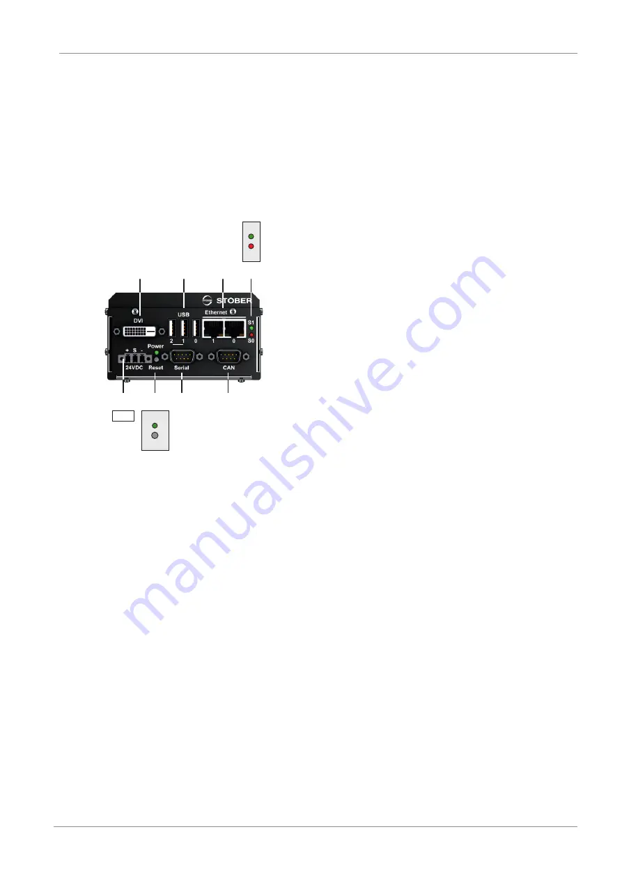
Fig. 22: Connection overview using the example of the MC6x01
1
DVI
5
External 24 V
DC
power supply
2
3 × USB
6
Power LED / reset button
3
2 × Ethernet (Ethernet and EtherCAT)
7
Serial RS-232
4
2 × status LEDs / CANopen
8
CAN


