UM2027
Triacs
and AC switches insulated control
DocID029048 Rev 1
29/37
9
Triacs and AC switches insulated control
The VIPer26LD flyback provides a 5 V DC output voltage. The high terminal of this output
is connected to the line (terminal L1, after the EMI filter); this is why this output is called
VCC_AC, as it is referenced to the AC voltage, not to the DC bus. Moreover, as the upper
level of this output is connected to L1, it allows a negative supply to be implemented. A
negative supply is indeed required to sink the current from the AC switch gates. All the AC
switches on the STEVAL-IHT008V1 boards are so controlled in quadrants 2 and 3. For
more information regarding this, refer to AN3168 or AN4564.
As the MCU is not at the same ground reference as AC switches, optocouplers are needed
to control them. The optocoupler must be chosen to generate enough output current
(optocoupler collector current) to control AC switches according to the input current
(optocoupler LED forward current). In this case, the optocoupler gain, expressed as a
current transfer ratio (CTR), must be chosen according to the equation below, where IGT is
the AC switch gate current and IO_MCU is the output current supplied by the MCU to
control the optocoupler LED.
Given the AC switch gate current (IGT), the gate resistor to limit the AC switch gate current
can be defined according to the following equation, where VCC_AC is the power supply to
provide the gate current to all AC switches and VCE(SAT)_Opto is the transistor collector-
emitter of the optocoupler.
In our case, the AC switches (T1 to T5) are controlled by using the IS127 optocoupler (U1,
U2, U3, U4 and U5), see . The CTR of this optocoupler is 1000 and can provide a 20 mA
gate current (which is two times above the 10 mA IGT of the ACS108-8Sx, ACST210 and
Z0109 devices) with R
17
= R
19
= R
20
= R
21
= R
22
= 91 Ω.
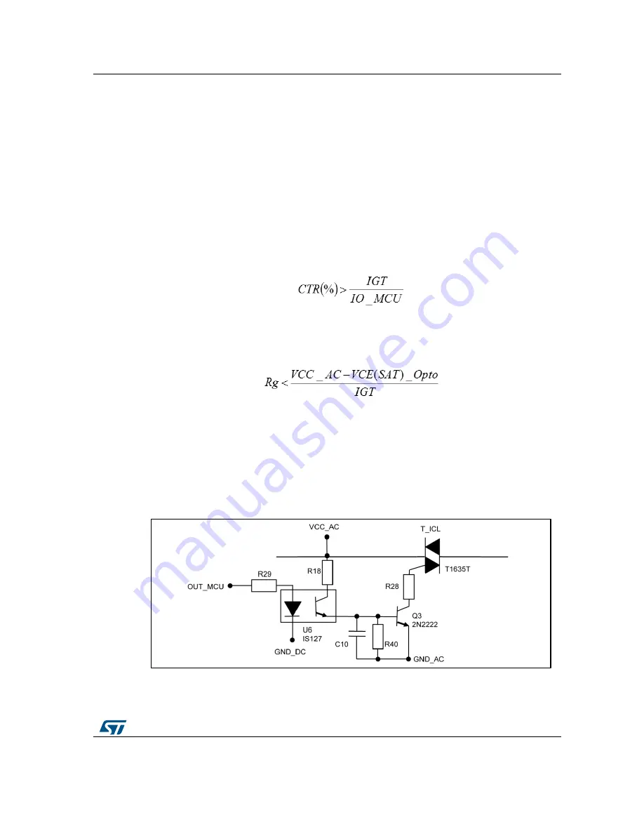
To control the T_ICL AC switch, an optocoupler (U6) associated with a NPN transistor (Q3)
is used as shown in the following figure. Moreover, to improve the NPN transistor immunity,
a RC filter is connected between the base and the emitter of the NPN transistor (R
40
= 4.7
kΩ and C10 = 1 nF).
Figure 20: T_ICL AC switch insulated control
The gate resistance (R
28
) of the T_ICL AC switch is given in the equation below, where
VCC_AC is the power supply to provide the gate current to the AC switch, VCE(SAT)
NPN
is


