UM2027
Inrush-current
limitation
DocID029048 Rev 1
21/37
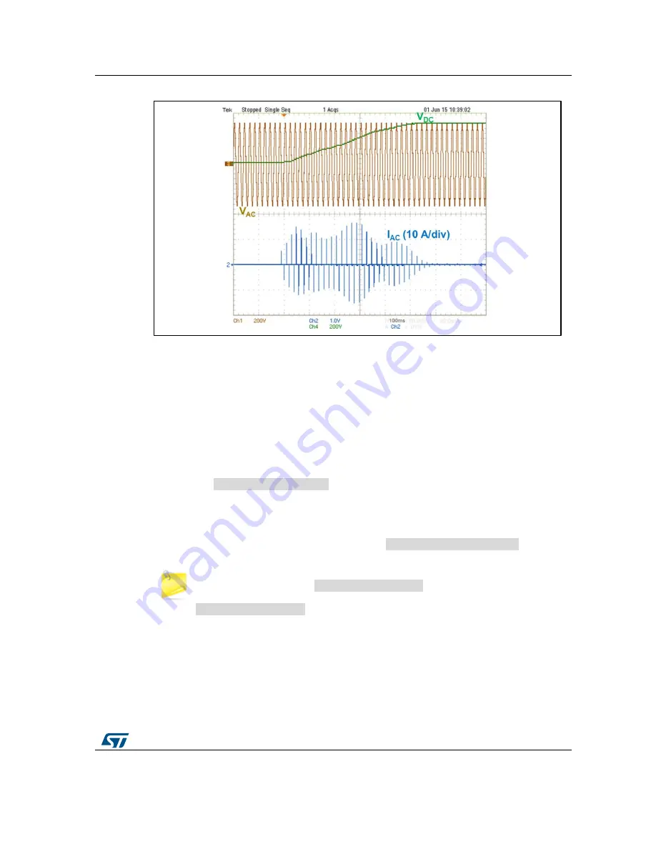
Figure 14: Inrush current during STEVAL-IHT008V1 startup on 230 V line (500 µF output DC
capacitor)
Here, the MCU firmware is the default program, so:
the first T_ICL turn-on is set to 410 µs before next line Zero Voltage. As the first gate
current pulse lasts 50 µs, the gate current can be removed 360 µs before the next half
cycle and avoid full-wave conduction in the next half-cycle.
This 360 µs interval includes the ZVS signal delay (which can equal up to 70 µs, see
Section 8: "AC voltage monitoring and zero-voltage synchronisation"
), the MCU data
treatment time before setting the ICL_CTRL I/O pin to high (40 µs) and the delay
required transistor Q3 to become unsaturated, which drives T_ICL (150 µs). The total
delay time therefore equals 260 µs; 150 µs is added as the safety margin. This delay
is called
ICL_TRIAC_OFF_Delay
in the firmware. As the timer is launched both in
count-up and count-down modes, half of the desired value must be given in this
parameter.
Next T_ICL turn-on occurs 50 µs sooner each time when the "MAX_INRUSH
CURRENT" potentiometer is set to the DEFAULT position. This minimum step value is
defined in the directive section of the firmware (
Step_Phase_Control_Min
).
the DEFAULT position corresponds to the slowest output DC capacitor charge
and therefore the shortest
Step_Phase_Control
value. When the
"MAX_INRUSH CURRENT" potentiometer is turned clockwise after point 1,
Step_Phase_Control
increases roughly linearly from around 50 µs (position
1) to 600 µs (position 6).
When the T_ICL Triac turn-on delay goes lower than 3 ms, the Triac is triggered by a
DC gate current.
Figure 15: "Triac current zoom for the highest peak current during start-up"
shows that, in
these conditions, the inrush peak current remains below 17.4 A. The RMS current is thus
far below the 16.1 A limit (as explained below). This means that the relative variation is
lower than 3.3%. It is therefore not necessary to check the duration of the accumulated


