


Evaluation board
objectives
UM2027
8/37
DocID029048 Rev 1
one bypass relay (refer to RLIM and S1 on
Figure 5: "Solution using relays to limit
inrush current and standby losses"
).
Case 3: as above, but circuits used solely for demonstration purposes and which
consume undesired power at standby are disconnected. These circuits are the "HV
Capacitor Discharge" circuit (where R7 and R10 are connected to the DC bus) and the
"HVDC" LED (D2) indicating presence of high voltage (where D1, R12, and R13 are
connected to the DC bus).
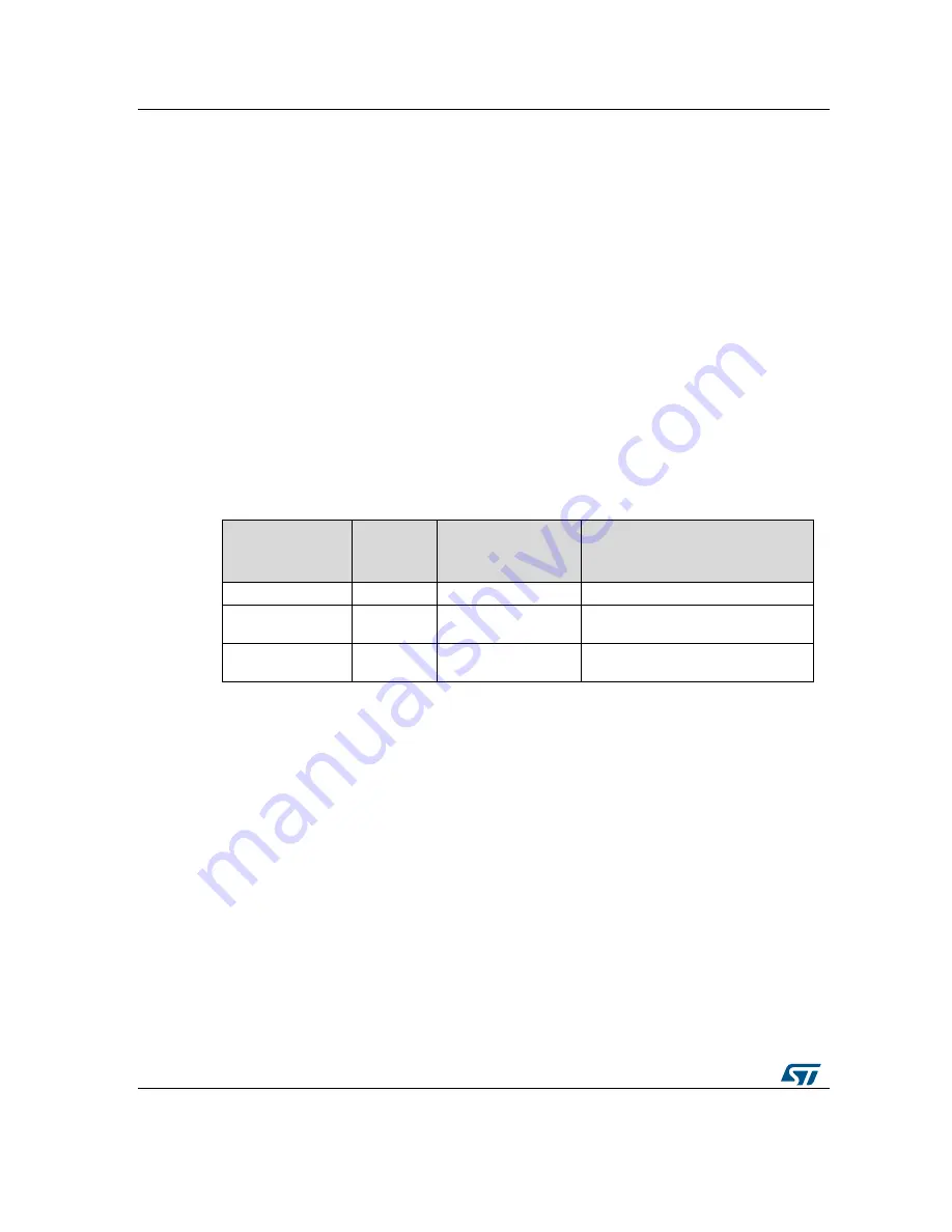
Table 1: "Comparison of standby losses"
gives the experimental results for the three cases
in the three different modes of operation (230 V, 110 V line voltage in rectifier and doubler
mode). The tests results clearly show that the Triac solution is the only one to achieve a
power consumption level lower than 0.5 W, as currently required by European directive
2005/32/EC.
The losses measured for case 3 are mainly due to the resistor divider circuit (R9, R11,
R14, R16) used to balance the voltage across the 2 series capacitors (C1 and C9) and the
other resistor divider circuit (R30, R31) used to sense the HVDC voltage. On our board, the
HVDC voltage is monitored to check proper soft-start operation and to avoid that the DC
capacitor charge duration is too long (if, for example, a load remains connected to the DC
bus before start-up). In standard circuits, however, such a voltage sensor is often required
(to start the PFC or the DC-DC supplies, for example).
T
he losses for a 230 V rectified voltage equal 520 mW for the 200 kΩ R9, R11, R14 and
R16 equivalent resistor, and 52 mW for the 2 MΩ R30 and R31 equivalent resistor.
Table 1: Comparison of standby losses
Mode of
operation
Case 1
T_ICL OFF
Case 2
PTC instead of Triac
Case 3
PTC discharge and D2 LED
circuits removed
230 V
125 mW
1.7 W
950 mW
110 V / rectifier
mode
70 mW
0.6 W
280 mW
110 V / doubler
mode
70 mW
1.5 W
860 mW


