INSTALLATIoN
Preparation
www.stiebel-eltron.com
HSBC 300 cool | HSBC 300 L cool |
41
EN
GL
ISH
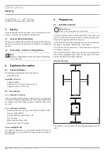
Joining appliance sections
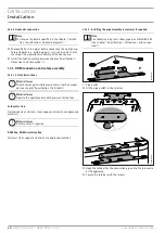
Rejoin the appliance sections in reverse order.
The positioning aids and the dotted line marking provide assis-
tance when positioning and inserting the upper appliance section
into the guide groove on the lower section:
D
00000
80
346
1
5
4
3
2
1 Handle
2 Guide pin
3 Dotted line (perforation in the panel)
4 Guide groove
5 Positioning aid
D
00000
57
300
1
1 Dotted line (perforation in the panel)
f
f
Place the upper appliance section onto the lower appliance
section along the dotted line.
D
00000
746
14
f
f
Slide the upper appliance section to the back until it is flush
with the lower appliance section. If the appliance sections
are joined correctly, the final position is determined by the
guide groove and guide pin.
f
f
Secure the tabs on the appliance front.
f
f
Fit the side profile strips.
f
f
Fit insulation segment 3 and the 4 hydraulic hoses.
f
f
Connect the push-fit connectors of the 4 hydraulic connec-
tions. Ensure that the spring clips click into place.
f
f
Insert the "heating sensor" at the buffer cylinder.
f
f
Lay the sensor lead in the guide groove provided for this
purpose.
f
f
Fit insulation segment 2.
f
f
Fit insulation segment 1.
f
f
Fit the front casing.

