background image

60

 | HSBC 300 cool | HSBC 300 L cool www.stiebel-eltron.com

TABLe deS MATIÈreS | reMArqUeS PArTICULIÈreS 


reMArqUeS 

PArTICULIÈreS


- L’appareil peut être utilisé par des enfants de 

8 ans et plus, ainsi que par des personnes aux 

facultés physiques, sensorielles ou mentales 

réduites, ou par des personnes sans expé-

rience, s’ils sont sous surveillance ou qu’ils 

ont été formés à l’utilisation en toute sécurité 

de l’appareil, et s’ils ont compris les dangers 

encourus. Ne laissez pas les enfants jouer 

avec l’appareil. Ne confiez pas le nettoyage ni 

les opérations de maintenance réservées aux 

utilisateurs à des enfants sans surveillance.


- Le raccordement au secteur n’est autorisé 

qu’en installation fixe. L’appareil doit pouvoir 

être mis hors tension par un dispositif de cou-

pure omnipolaire ayant une ouverture mini-

male des contacts de 3 mm.


- Respectez toutes les prescriptions et régle-

mentations nationales et locales en vigueur.


- Respectez les distances minimales (voir cha-

pitre « Installation / Travaux préparatoires / 

Lieu d’installation »).


- L’installation, la mise en service, la main-

tenance et les réparations de cet appareil 

doivent exclusivement être confiées à un 

installateur.

Ballon d’eau chaude sanitaire


- Vidangez l’appareil comme indiqué au cha-

pitre « Installation / Maintenance / Vidange 

du ballon d’eau chaude sanitaire ».


- Tenez compte de la pression maximale admis-

sible (voir le chapitre « Installation / Données 

techniques / Tableau des données »).

REMARQUES PARTICULIÈRES
UTILISATION

1. 

Remarques générales ������������������������������������� 61

1.1 

Documentation applicable ������������������������������������ 61

1.2 

Consignes de sécurité ������������������������������������������ 61

1.3 

Autres pictogrammes utilisés dans cette 

documentation �������������������������������������������������� 61

1.4 

Remarques apposées sur l’appareil ������������������������ 61

1.5 

Unités de mesure ����������������������������������������������� 61

2. 

Sécurité ����������������������������������������������������� 62

2.1 

Utilisation conforme ������������������������������������������� 62

2.2 

Consignes de sécurité générales ���������������������������� 62

2.3 

Label de conformité �������������������������������������������� 62

3. 

Compatibilité de l’appareil �������������������������������� 62

4. 

Description de l’appareil ���������������������������������� 62

5. 

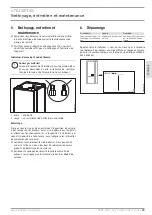
Nettoyage, entretien et maintenance �������������������� 63

6. 

Dépannage �������������������������������������������������� 63

INSTALLATION

7. 

Sécurité ����������������������������������������������������� 64

7.1 

Consignes de sécurité générales ���������������������������� 64

7.2 

Prescriptions, normes et réglementations����������������� 64

8. 

Description de l’appareil ���������������������������������� 64

8.1 

Fourniture �������������������������������������������������������� 64

8.2 

Accessoires ������������������������������������������������������� 64

9. 

Travaux préparatoires ������������������������������������� 64

9.1 

Lieu d’installation ����������������������������������������������� 64

9.2 

Transport, manutention et mise en place ������������������ 65

10. 

Montage ����������������������������������������������������� 70

10.1  Mise en place de l’appareil ����������������������������������� 70
10.2  Raccordement de l’eau chaude et soupape de sécurité  70
10.3  Raccordement de l’eau froide et du groupe de sécurité 74
10.4  Remplissage de l’installation ��������������������������������� 76
10.5  Purge de l’appareil ��������������������������������������������� 76

11. 

Raccordement électrique ���������������������������������� 76

11.1  Tension de commande ����������������������������������������� 77
11.2  Très basse tension ���������������������������������������������� 78
11.3  Corps de chauffe additionnel ��������������������������������� 78
11.4  Mise en place des sondes ������������������������������������� 78

12. 

Mise en service ��������������������������������������������� 79

12.1  Remise de l’appareil au client �������������������������������� 79

13. 

Mise hors service ������������������������������������������ 79

14. 

Maintenance ������������������������������������������������ 79

15. 

Données techniques ��������������������������������������� 80

15.1  Cotes et raccordements ���������������������������������������� 80
15.2  Schéma électrique ���������������������������������������������� 82
15.3  Schémas hydrauliques ����������������������������������������� 84

16. 

Données techniques ��������������������������������������� 85

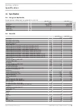
16.1  Indications relatives à la consommation énergétique ��� 85
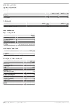
16.2  Tableau des données ������������������������������������������� 85
16.3  Accessoires ������������������������������������������������������� 86

GARANTIE
ENVIRONNEMENT ET RECYCLAGE

UTILISATIoN eT INSTALLATIoN

Tour hydraulique combinée

Содержание HSBC 300 cool

Страница 1: ...TALLATION OPERATION AND INSTALLATION UTILISATION ET INSTALLATION BEDIENING EN INSTALLATIE USO E INSTALLAZIONE Integralspeicher Integral cylinder Ballon combiné Combiboiler Caldaia integrale HSBC 300 cool HSBC 300 L cool ...

Страница 2: ...aximal zulässigen Druck siehe Kapitel Installation Technische Daten Datentabelle BESONDERE HINWEISE BEDIENUNG 1 Allgemeine Hinweise 3 1 1 Mitgeltende Dokumente 3 1 2 Sicherheitshinweise 3 1 3 Andere Markierungen in dieser Dokumentation 3 1 4 Hinweise am Gerät 3 1 5 Maßeinheiten 3 2 Sicherheit 4 2 1 Bestimmungsgemäße Verwendung 4 2 2 Allgemeine Sicherheitshinweise 4 2 3 Prüfzeichen 4 3 Gerätekompat...

Страница 3: ... Art der Gefahr Verletzung Stromschlag Verbrennung Verbrennung Verbrühung 1 2 3 Signalworte SIGNALWORT Bedeutung GEFAHR Hinweise deren Nichtbeachtung schwere Verletzungen oder Tod zur Folge haben WARNUNG Hinweise deren Nichtbeachtung schwere Verletzungen oder Tod zur Folge haben kann VORSICHT Hinweise deren Nichtbeachtung zu mittelschweren oder leichten Verletzungen führen kann 1 3 Andere Markieru...

Страница 4: ...chener Spannungsversorgung ist der aktive Frostschutz der Anlage nicht gewährleistet f f Unterbrechen Sie die Spannungsversorgung auch außerhalb der Heizperiode nicht 2 3 Prüfzeichen Siehe Typenschild am Gerät 3 Gerätekompatibilität Sie können das Gerät in Kombination mit den folgenden Luft Was ser Wärmepumpen betreiben HSBC 300 cool WPL 10 AC WPL 15 20 25 AC S WPL 19 24 I HSBC 300 L cool WPL 09 1...

Страница 5: ...jedes Wasser scheidet bei hohen Temperaturen Kalk aus Dieser setzt sich im Gerät ab und beeinflusst die Funktion und Lebensdauer des Gerätes Der Fachhandwerker der die örtliche Wasserqualität kennt wird Ihnen den Zeitpunkt für die nächste Wartung nennen f f Kontrollieren Sie regelmäßig die Armaturen Kalk an den Armaturausläufen können Sie mit handelsüblichen Entkal kungsmitteln entfernen f f Betät...

Страница 6: ...zulässigen Drucküber schreitungen 8 2 2 Weiteres Zubehör Pumpenbaugruppe für einen gemischten Heizkreis HSBC 3 HKM Rohrbausatz RBS SBC Zusatz Heizelement HSBC 3 HE Druckschläuche Enthärtungsarmatur HZEA Temperaturfühler für Kühlung Rohrbausatz RBS SBC Die hydraulischen Anschlüsse können mit dem als Zubehör er hältlichen Rohrbausatz RBS SBC hinter dem Trinkwarmwasser speicher nach oben geführt werd...

Страница 7: ... Sie die beiliegenden 4 Stellfüße ein f f Heben Sie das Gerät von der Palette Falls enge Türen oder Gänge die Einbringung behindern können Sie den oberen vom unteren Geräteteil trennen wie in den folgen den Kapiteln beschrieben 9 2 1 Frontverkleidung demontieren montieren D0000080283 f f Entfernen Sie die 2 Sicherungsschrauben an der Oberseite der Frontverkleidung f f Haken Sie die Frontverkleidun...

Страница 8: ...Installation Vorbereitungen 8 HSBC 300 cool HSBC 300 L cool www stiebel eltron com 9 2 2 Übersicht Dämmelemente D0000080535 1 2 3 1 Dämmelement 1 2 Dämmelement 2 3 Dämmelement 3 ...

Страница 9: ...nehmen Sie Dämmelement 1 f f Entnehmen Sie Dämmelement 2 D0000080287 f f Ziehen Sie den Fühler Heizung am Pufferspeicher heraus D0000080288 f f Lösen Sie das Fühlerkabel aus der Führungsnut D0000080289 f f Lösen Sie die Steckverbinder der 4 hydraulischen Anschlüsse Ziehen Sie dazu die Federklemmen mit einem Schraubendre her bis zum Anschlag heraus f f Ziehen Sie die hydraulischen Anschlüsse wie da...

Страница 10: ...lichen Profilleisten nach oben aus D0000080343 f f Lösen Sie die 4 Schrauben an den Laschen vorn am Gerät D0000074613 f f Ziehen Sie den oberen Geräteteil nach vorn D0000080345 1 1 Griffschiene f f Kippen Sie den oberen Geräteteil nach hinten Nutzen Sie die Griffschiene für besseren Halt D0000080347 f f Stellen sie den oberen Geräteteil auf einer Unterlage ab um Beschädigungen zu vermeiden ...

Страница 11: ...teteil an der gestrichelten Linie auf den unteren Geräteteil D0000074614 f f Schieben Sie den oberen Geräteteil nach hinten bis er bün dig zum unteren Geräteteil ist Wenn Sie die Geräteteile kor rekt zusammenfügen ist die Endposition durch Führungsnut und Führungsbolzen vorgegeben f f Befestigen Sie die Laschen vorn am Gerät f f Montieren Sie die seitlichen Profilleisten f f Montieren Sie Dämmelem...

Страница 12: ...e Druckverluste kann die maximal zulässige Leitungslänge zwischen Gerät und Wärmepumpe variieren Als Richtwert gehen Sie von einer maximalen Leitungslänge von 10 m und einem Leitungs durchmesser von 22 28 mm aus f f Isolieren Sie die Vor und Rücklaufleitung gemäß der regio nalen Vorschriften f f Schließen Sie die hydraulischen Anschlüsse flachdichtend an Druckschläuche gegen Körperschall Übertragu...

Страница 13: ...ppen von den Übergangsnippeln ab Montage HSBC 3 HKM 1 2 Nm D0000081576 f f Bringen Sie den 3 Wege Mischer mit Stellmotor in die kor rekte Einbaulage D0000080376 7 8 10 Rohrbaugruppe eingesetzt 7 Dämmmatte für 3 Wege Mischer 8 Dämmmatte für 3 Wege Mischer und Heizkreis Umwälzpumpe 10 Formteile für 3 Wege Mischer f f Setzen Sie die Rohrbaugruppe ein f f Legen Sie die Flachdichtungen in die Überwurfm...

Страница 14: ...isch an siehe Kapitel Installation Elektri scher Anschluss Steuerspannung 10 2 3 Ggf Zubehör Zusatz Heizelement HSBC 3 HE montieren D0000080386 2 1 1 Blindflansch 2 Dämmelement f f Entnehmen Sie das vor der Flanschplatte liegende Dämmelement f f Demontieren Sie den Blindflansch 9 0 1 3 5 D0000080539 1 1 Erdungskontakt PE f f Bringen Sie das Zusatz Heizelement in die korrekte Ein baulage Orientiere...

Страница 15: ...Hinweis Im Lieferumfang des Zusatz Heizelements befinden sich zwei identische Schaltplanaufkleber zum Überkleben der Position HSBC 3 HE Zubehör X2 11 im Elektroschalt plan auf der Rückseite der Frontverkleidung in dieser Anleitung siehe Kapitel Installation Technische Daten Elektroschaltplan f f Kleben Sie nach dem Einbau des Zusatz Heizele ments jeweils einen Schaltplanaufkleber an den entspreche...

Страница 16: ...mal zulässige Druck darf nicht überschritten werden siehe Kapitel Technische Daten Datentabelle Sachschaden Das Gerät muss mit Druck Armaturen betrieben werden Kaltwasserleitung Als Werkstoffe sind feuerverzinkter Stahl Edelstahl Kupfer und Kunststoff zugelassen Sachschaden Ein Sicherheitsventil ist erforderlich Warmwasserleitung Zirkulationsleitung Als Werkstoffe sind Edelstahl Kupfer und Kunstst...

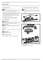
Страница 17: ...Zirkulation siehe Kapitel Technische Daten Maße und Anschlüsse f f Schließen Sie die Zirkulationsleitung an 10 3 4 Trinkwasser Anschluss und Sicherheitsgruppe f f Spülen Sie die Rohrleitungen gut durch f f Montieren Sie die Warmwasser Auslaufleitung und die Kaltwasser Zulaufleitung siehe Kapitel Technische Daten Maße und Anschlüsse Schließen Sie die hydraulischen An schlüsse flachdichtend an f f I...

Страница 18: ...en Fach handel bezogen werden Sachschaden Schalten Sie die Anlage vor der Befüllung nicht elektrisch ein 10 4 1 Heizungsanlage befüllen D0000080425 f f Befüllen Sie die Heizungsanlage über das Entleerungsventil f f Entlüften Sie das Rohrleitungssystem 10 4 2 Trinkwarmwasserspeicher befüllen f f Befüllen Sie den Trinkwarmwasserspeicher über den An schluss Kaltwasser Zulauf f f Öffnen Sie alle nachg...

Страница 19: ...rät und die Steuerung getrennt ab Sachschaden Beachten Sie das Typenschild Die angegebene Spannung muss mit der Netzspannung übereinstimmen Hinweis Es können Ableitströme bis 5 mA auftreten Hinweis Die Genehmigung des zuständigen Energieversorgungs unternehmens zum Anschluss des Gerätes muss vorlie gen Der Anschlusskasten des Gerätes befindet sich hinter der Front verkleidung siehe Kapitel Vorbere...

Страница 20: ...r Brücke zwischen L und 2 einen Tem peraturwächter für die Fußbodenheizung installieren XD03 3 Anschlussklemme Steuerung Mischer Mischer Stellmotor Heizkreis 2 UV Umschaltventil Heizung WW 11 2 Sicherheitskleinspannung D0000080433 XD04 Anschlussklemme Sicherheitskleinspannung T MK Temperaturfühler Mischerkreis optional T KUE Temperaturfühler bei Flächenkühlung optional T WW Temperaturfühler Warmwa...

Страница 21: ...tes anfordern Wenn Sie das Gerät gewerblich einsetzen beachten Sie bei der Inbetriebnahme ggf die Festlegungen der Betriebssicherheitsver ordnung Weitere Auskünfte hierzu erteilt die zuständige Über wachungsstelle in Deutschland z B TÜV 12 1 Übergabe des Gerätes f f Erklären Sie dem Benutzer die Funktion des Gerätes und ma chen Sie ihn mit dem Gebrauch des Gerätes vertraut f f Weisen Sie den Benut...

Страница 22: ...im Entleeren kann heißes Wasser austreten f f Schließen Sie das Absperrventil in der Kaltwasser Zulaufleitung f f Öffnen Sie die Warmwasserventile aller Entnahmestellen f f Entleeren Sie den Trinkwarmwasserspeicher über den An schluss Kaltwasser Zulauf Trinkwarmwasserspeicher reinigen und entkalken Sachschaden Verwenden Sie keine Entkalkungspumpe und keine Ent kalkungsmittel für die Reinigung des ...

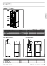
Страница 23: ...3 593 10 20 d01 e02 d02 e01 c01 c10 c06 b01 D0000077428 HSBC 300 cool HSBC 300 L cool b01 Durchführung elektr Leitungen c01 Kaltwasser Zulauf Außengewinde G 1 G 1 c06 Warmwasser Auslauf Außengewinde G 1 G 1 c10 Zirkulation Außengewinde G 1 2 G 1 2 d01 WP Vorlauf Durchmesser mm 28 28 d02 WP Rücklauf Durchmesser mm 28 28 e01 Heizung Vorlauf Durchmesser mm 22 22 e02 Heizung Rücklauf Durchmesser mm 22...

Страница 24: ...5 9 5 h53 Fühler Heizung Durchmesser mm 9 5 9 5 i01 Flansch Außendurchmesser Anzugsdrehmoment mm Nm 140 45 140 45 i18 Schutzanode Innengewinde G 1 1 4 G 1 1 4 15 1 1 Zubehör HSBC 3 HKM 293 393 771 e31 e30 D0000080455 HSBC 3 HKM RBS SBC c01 Kaltwasser Zulauf Durchmesser mm 22 22 c06 Warmwasser Auslauf Durchmesser mm 22 22 c10 Zirkulation Durchmesser mm 12 12 e30 Heizung Vorlauf gemischt Durchmesser...

Страница 25: ... T Puffer X1 4 T WW X1 8 T KUE X1 11 T MK X1 6 BT06 BT13 BT20 N 2 3 L 1 3 2 A B 1 KF 17 XD06 1 HSBC 3 HE Zubehör X2 11 L MA14 M 1 N MKP X2 4 6 1 2 5 3 3 4 2 N L HKP X2 3 2 MISCHER X2 14 N 2 L UV X2 8 1 4 5 3 6 2 N LA LZ 2 1 Vorderwand Front cover Deckelblech Top cover Netz 220 240V L M 1 N L M 1 N N 2 L 1 1 7 8 9 N L 10 1 2 PWM X1 16 XD04 9 XD06 2 BN PWM IN BU com BN PWM IN BU com MA15 3 N AB B AB...

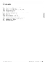
Страница 26: ...ei HSBC 300 L cool und TSBC 300 L plus MA15 Motor Umschaltventil Heizung WW MA19 Motor Mischerventil Heizkreis 2 XD04 Anschlussklemme Kleinspannung XD06 1 Anschlussklemme Beheizung Zubehör HSBC 3 HE XD06 2 Anschlussklemme Beheizung Zubehör HSBC 3 HE XD03 1 Anschlussklemme Steuerung Netz Pufferladepumpe XD03 2 Anschlussklemme Steuerung Heizkreispumpe Pumpe Heizkreis 2 XD03 3 Anschlussklemme Steueru...

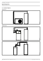
Страница 27: ...Installation Technische Daten DEUTSCH www stiebel eltron com HSBC 300 cool HSBC 300 L cool 27 15 3 Hydraulikschaltpläne HSBC 300 cool D0000080569 HSBC 300 L cool D0000080571 D0000080570 ...

Страница 28: ...gbare Druckdifferenz Umwälzpumpe Heizkreis 2 optional bei 1 0 m h hPa 665 665 Externe verfügbare Druckdifferenz Umwälzpumpe Heizkreis 2 optional bei 1 5 m h hPa 518 518 Externe verfügbare Druckdifferenz Umwälzpumpe Heizkreis 2 optional bei 2 0 m h hPa 189 189 Einsatzgrenzen Max zulässiger Druck Trinkwarmwasserspeicher MPa 1 0 1 0 Prüfdruck Trinkwarmwasserspeicher MPa 1 5 1 5 Max Durchflussmenge l ...

Страница 29: ...asser mm 22 Anschluss Zirkulation mm 12 Ausführungen Geeignet für SBC 300 cool plus und 300 L cool plus Pumpenbaugruppe HSBC 3 HKM HSBC 3 HKM 238825 Anschlüsse Anschluss Heizkreis mm 22 Zusatz Heizelement HSBC 3 HE HSBC 3 HE 200025 Elektrische Daten Anschlussleistung 230 V kW 2 Nennspannung V 230 Phasen 1 N PE Frequenz Hz 50 Einsatzgrenzen Temperatureinstellbereich C 35 80 Max zulässiger Druck MPa...

Страница 30: ...ren Etwaige ausgewechselte Teile werden unser Eigentum Für die Dauer und Reichweite der Garantie übernehmen wir sämtliche Material und Montagekosten Soweit der Kunde wegen des Garantiefalles aufgrund gesetzli cher Gewährleistungsansprüche gegen andere Vertragspartner Leistungen erhalten hat entfällt eine Leistungspflicht von uns Soweit eine Garantieleistung erbracht wird übernehmen wir keine Haftu...

Страница 31: ...es der Dualen Systeme in Deutschland Entsorgung von Altgeräten in Deutschland Geräteentsorgung Die mit diesem Symbol gekennzeichneten Geräte dür fen nicht mit dem Hausmüll entsorgt werden Als Hersteller sorgen wir im Rahmen der Produktverantwor tung für eine umweltgerechte Behandlung und Verwertung der Altgeräte Weitere Informationen zur Sammlung und Ent sorgung erhalten Sie über Ihre Kommune oder...

Страница 32: ...ee chapter Installation Specification Data table SPECIAL INFORMATION OPERATION 1 General information 33 1 1 Relevant documents 33 1 2 Safety instructions 33 1 3 Other symbols in this documentation 33 1 4 Information on the appliance 33 1 5 Units of measurement 33 2 Safety 34 2 1 Intended use 34 2 2 General safety instructions 34 2 3 Test symbols 34 3 Appliance compatibility 34 4 Appliance descript...

Страница 33: ...ols type of risk Symbol Type of risk Injury Electrocution Burns burns scalding 1 2 3 Keywords KEYWORD Meaning DANGER Failure to observe this information will result in serious injury or death WARNING Failure to observe this information may result in serious injury or death CAUTION Failure to observe this information may result in non seri ous or minor injury 1 3 Other symbols in this documentation...

Страница 34: ...power supply is interrupted f f Never interrupt the power supply even outside the heating season 2 3 Test symbols See type plate on the appliance 3 Appliance compatibility The appliance can be operated in conjunction with the following air water heat pumps HSBC 300 cool WPL 10 AC WPL 15 20 25 AC S WPL 19 24 I HSBC 300 L cool WPL 09 17 ICS IKCS classic WPL 19 24 IK WPF 04 05 07 10 cool 4 Appliance ...

Страница 35: ...Almost every type of water will deposit limescale at high temper atures This settles inside the appliance and affects both perfor mance and service life A qualified contractor who knows the local water quality will tell you when the next service is due f f Check the taps regularly Limescale deposits at the tap out lets can be removed using commercially available descaling agents f f Regularly acti...

Страница 36: ... pressure 8 2 2 Additional accessories Pump assembly for a heating circuit with mixer HSBC 3 HKM Pipe assembly RBS SBC Auxiliary heating element HSBC 3 HE Pressure hoses Water softening fitting HZEA Temperature sensor for cooling Pipe assembly RBS SBC The hydraulic connections can be routed upwards at the rear of the DHW cylinder using the RBS SBC pipe assembly available as an accessory 9 Preparat...

Страница 37: ...pliance and screw the 4 adjustable feet into the appliance f f Lift the appliance off the pallet If narrow doors or hallways hinder handling you can separate the upper and lower sections of the appliance as described in the following chapters 9 2 1 Removing fitting the front casing D0000080283 f f Remove the 2 locking screws on the top of the front casing f f Unhook the front casing towards the to...

Страница 38: ...stallation Preparation 38 HSBC 300 cool HSBC 300 L cool www stiebel eltron com 9 2 2 Overview of insulation segments D0000080535 1 2 3 1 Insulation segment 1 2 Insulation segment 2 3 Insulation segment 3 ...

Страница 39: ...t D0000080284 f f Remove insulation segment 1 f f Remove insulation segment 2 D0000080287 f f Pull out the heating sensor at the buffer cylinder D0000080288 f f Release the sensor lead from the guide groove D0000080289 f f Disconnect the push fit connectors of the 4 hydraulic con nections To do this pull the spring clips fully out with a screwdriver f f Pull the hydraulic connectors as indicated D...

Страница 40: ...k the side profile strips D0000080343 f f Release the 4 screws on the tabs at the front of the appliance D0000074613 f f Pull the upper section of the appliance towards the front D0000080345 1 1 Handle f f Tip the upper section of the appliance backwards Use the handle for improved grip D0000080347 f f Place the upper section of the appliance on a base to prevent damage ...

Страница 41: ...tion onto the lower appliance section along the dotted line D0000074614 f f Slide the upper appliance section to the back until it is flush with the lower appliance section If the appliance sections are joined correctly the final position is determined by the guide groove and guide pin f f Secure the tabs on the appliance front f f Fit the side profile strips f f Fit insulation segment 3 and the 4...

Страница 42: ...es f f The maximum permissible line length between the appli ance and the heat pump will vary depending on the version of the heating system pressure drop As a standard value assume a maximum line length of 10 m and a pipe diameter of 22 28 mm f f Insulate the flow and return lines in accordance with regional regulations f f Connect the hydraulic connections with flat gaskets Pressure hoses agains...

Страница 43: ...d unscrew the dummy caps from the adaptors HSBC 3 HKM installation 1 2 Nm D0000081576 f f Move the 3 way mixer with servomotor to the correct instal lation position D0000080376 7 8 10 Pipe assembly inserted 7 Insulation mat for 3 way mixer 8 Insulation mat for 3 way mixer and heating circuit pump 10 Profiles for 3 way mixer f f Insert the pipe assembly f f Insert the flat gaskets into the union nu...

Страница 44: ...nstallation Electrical connection Control voltage 10 2 3 If necessary install an HSBC 3 HE auxiliary heating element as an accessory D0000080386 2 1 1 Blank flange 2 Insulation segment f f Remove the insulation segment in front of the flange plate f f Remove the blank flange 9 0 1 3 5 D0000080539 1 1 Earthing contact PE f f Move the auxiliary heating element into the correct instal lation position...

Страница 45: ...GNYE Note The auxiliary heating element standard delivery in cludes two identical wiring diagram labels for covering HSBC 3 HE accessory X2 11 on the wiring diagram On the back of the front casing In these instructions see chapter Installation Specification Wiring diagram f f After installation of the auxiliary heating element affix the wiring diagram labels in the corresponding places f f Wire up...

Страница 46: ...es The maximum permissible pressure must not be exceed ed see chapter Specification Data table Material losses Operate the appliance only with pressure tested taps Cold water line Galvanised steel stainless steel copper and plastic are approved materials Material losses A safety valve is required DHW line DHW circulation line Stainless steel copper and plastic are approved materials 10 3 2 Install...

Страница 47: ...let line Please note that depending on the supply pressure you may also need a pressure reducing valve f f Size the drain pipe so that water can drain off unimpeded when the safety valve is fully opened f f The safety valve drain aperture must remain open to atmosphere f f Install the safety valve drain pipe with a constant fall to the drain 10 4 Filling the system Heating circuit water quality Ca...

Страница 48: ... Before any work on the appliance disconnect all poles from the power supply WARNING Electrocution The connection to the power supply must be in the form of a permanent connection Ensure the appliance can be separated from the power supply by an isolator that dis connects all poles with at least 3 mm contact separation This requirement can be met by using contactors circuit breakers fuses MCBs etc...

Страница 49: ... for the underfloor heating system by remov ing the jumper between L and 2 XD03 3 Control terminal Mixer Mixer servomotor heating circuit 2 UV Diverter valve heating DHW 11 2 Safety extra low voltage D0000080433 XD04 Terminal safety extra low voltage T MK Temperature sensor mixer circuit optional T KUE Temperature sensor for area cooling optional T WW DHW temperature sensor T Puffer Temperature se...

Страница 50: ...rgeable service If the appliance is intended for commercial use observe the rules of the relevant Health Safety at Work Act during commissioning For further details check with your local authorising body in Germany for example this is the TÜV 12 1 Appliance handover f f Explain the appliance function to users and familiarise them with how it works f f Make users aware of potential dangers f f Hand...

Страница 51: ...via the drain valve Draining the DHW cylinder CAUTION Burns Hot water may escape during draining f f Close the shut off valve in the cold water inlet line f f Open the hot water taps on all draw off points f f Empty the DHW cylinder via the cold water inlet connection Cleaning and descaling the DHW cylinder Material losses Never use descaling pumps or descaling agents to clean the cylinder f f Cle...

Страница 52: ... 193 493 593 10 20 d01 e02 d02 e01 c01 c10 c06 b01 D0000077428 HSBC 300 cool HSBC 300 L cool b01 Entry electrical cables c01 Cold water inlet Male thread G 1 G 1 c06 DHW outlet Male thread G 1 G 1 c10 DHW circulation Male thread G 1 2 G 1 2 d01 Heat pump flow Diameter mm 28 28 d02 Heat pump return Diameter mm 28 28 e01 Heating flow Diameter mm 22 22 e02 Heating return Diameter mm 22 22 ...

Страница 53: ...ameter mm 9 5 9 5 h53 Sensor heating Diameter mm 9 5 9 5 i01 Flange External diameter Torque mm Nm 140 45 140 45 i18 Protective anode Female thread G 1 1 4 G 1 1 4 15 1 1 HSBC 3 HKM accessories 293 393 771 e31 e30 D0000080455 HSBC 3 HKM RBS SBC c01 Cold water inlet Diameter mm 22 22 c06 DHW outlet Diameter mm 22 22 c10 DHW circulation Diameter mm 12 12 e30 Heating flow mixed Diameter mm 22 22 e31 ...

Страница 54: ...er X1 4 T WW X1 8 T KUE X1 11 T MK X1 6 BT06 BT13 BT20 N 2 3 L 1 3 2 A B 1 KF 17 XD06 1 HSBC 3 HE Zubehör X2 11 L MA14 M 1 N MKP X2 4 6 1 2 5 3 3 4 2 N L HKP X2 3 2 MISCHER X2 14 N 2 L UV X2 8 1 4 5 3 6 2 N LA LZ 2 1 Vorderwand Front cover Deckelblech Top cover Netz 220 240V L M 1 N L M 1 N N 2 L 1 1 7 8 9 N L 10 1 2 PWM X1 16 XD04 9 XD06 2 BN PWM IN BU com BN PWM IN BU com MA15 3 N AB B AB A 2 1 ...

Страница 55: ...Motor buffer charging pump not for HSBC 300 L cool and TSBC 300 L plus MA15 Motor diverter valve heating DHW MA19 Motor mixing valve heating circuit 2 XD04 LV terminal XD06 1 Heater terminal accessories HSBC 3 HE XD06 2 Heater terminal accessories HSBC 3 HE XD03 1 Control terminal mains buffer charging pump XD03 2 Control terminal heating circuit pump pump heating circuit 2 XD03 3 Control terminal...

Страница 56: ...Installation Specification 56 HSBC 300 cool HSBC 300 L cool www stiebel eltron com 15 3 Hydraulic diagrams HSBC 300 cool D0000080569 HSBC 300 L cool D0000080571 D0000080570 ...

Страница 57: ...rnal available pressure differential circulation pump heating circuit 2 optional at 1 0 m h hPa 665 665 External available pressure differential circulation pump heating circuit 2 optional at 1 5 m h hPa 518 518 External available pressure differential circulation pump heating circuit 2 optional at 2 0 m h hPa 189 189 Application limits Max permissible pressure DHW cylinder MPa 1 0 1 0 Test pressu...

Страница 58: ...on mm 22 DHW circulation connection mm 12 Versions Suitable for SBC 300 cool plus and 300 L cool plus Pump assembly HSBC 3 HKM HSBC 3 HKM 238825 Connections Heating circuit connection mm 22 Auxiliary heating element HSBC 3 HE HSBC 3 HE 200025 Electrical data Connected load 230 V kW 2 Rated voltage V 230 Phases 1 N PE Frequency Hz 50 Application limits Temperature setting range C 35 80 Max permissi...

Страница 59: ... be issued by those subsidiaries Such guarantee is only grant ed if the subsidiary has issued its own terms of guarantee No other guarantee will be granted We shall not provide any guarantee for appliances acquired in countries where we have no subsidiary to sell our products This will not affect warranties issued by any importers Environment and recycling We would ask you to help protect the envi...

Страница 60: ...tion Données techniques Tableau des données REMARQUES PARTICULIÈRES UTILISATION 1 Remarques générales 61 1 1 Documentation applicable 61 1 2 Consignes de sécurité 61 1 3 Autres pictogrammes utilisés dans cette documentation 61 1 4 Remarques apposées sur l appareil 61 1 5 Unités de mesure 61 2 Sécurité 62 2 1 Utilisation conforme 62 2 2 Consignes de sécurité générales 62 2 3 Label de conformité 62 ...

Страница 61: ...bouillantement 1 2 3 Mentions d avertissement MENTION D AVERTISSE MENT Signification DANGER Caractérise des consignes dont le non respect entraîne de graves lésions voire la mort AVERTISSEMENT Caractérise des consignes dont le non respect peut entraî ner de graves lésions voire la mort ATTENTION Caractérise des consignes dont le non respect peut entraî ner des lésions légères ou moyennement graves...

Страница 62: ...upée la protection hors gel de l installation n est plus assurée f f Vous ne devez pas couper l alimentation électrique même en dehors de la période de chauffage 2 3 Label de conformité Voir la plaque signalétique sur l appareil 3 Compatibilité de l appareil L appareil peut être utilisé en association avec les pompes à cha leur air eau suivantes HSBC 300 cool WPL 10 AC WPL 15 20 25 AC S WPL 19 24 ...

Страница 63: ...au entraînent l apparition de calcaire à des températures élevées Celui ci se dépose dans l appareil et affecte son fonctionnement et sa longévité L installateur qui connaît la qualité de l eau locale vous indiquera les intervalles de maintenance à respecter f f Contrôlez régulièrement les robinetteries Vous pouvez éli miner le tartre au niveau des becs de robinetterie avec les produits de détartr...

Страница 64: ... hydraulique pour circuit de chauffage mélangé HSBC 3 HKM Kit de tubes RBS SBC Corps de chauffe additionnel HSBC 3 HE Tuyaux antivibratoires Cartouche adoucissante HZEA Sonde de température pour rafraîchissement Kit de tubes RBS SBC Le kit de tubes RBS SBC disponible comme accessoire permet un raccordement hydraulique vers le haut à l arrière du ballon ECS 9 Travaux préparatoires 9 1 Lieu d instal...

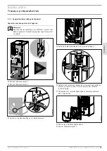
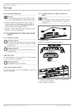
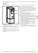
Страница 65: ... les 4 pieds réglables fournis f f Soulevez l appareil de la palette Si la mise en place de l appareil est entravée par des portes ou des passages trop étroits il est possible de séparer la partie su périeure de la partie inférieure comme décrit dans les chapitres suivants 9 2 1 Dépose repose du panneau avant D0000080283 f f Retirez les 2 vis d arrêt sur le dessus du panneau avant f f Décrochez le...

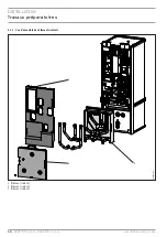
Страница 66: ...llation Travaux préparatoires 66 HSBC 300 cool HSBC 300 L cool www stiebel eltron com 9 2 2 Vue d ensemble des éléments isolants D0000080535 1 2 3 1 Élément isolant 1 2 Élément isolant 2 3 Élément isolant 3 ...

Страница 67: ...ère D0000080284 f f Retirez l élément isolant 1 f f Retirez l élément isolant 2 D0000080287 f f Sortez la Sonde chauffage du ballon tampon D0000080288 f f Sortez le câble de sonde de la rainure de guidage D0000080289 f f Détachez les manchons rapides des 4 raccords hydrauliques Utilisez un tournevis pour tirer les agrafes des raccords jusqu en butée f f Débranchez les raccords hydrauliques comme r...

Страница 68: ...atérales par le haut D0000080343 f f Desserrez les 4 vis des brides situées à l avant de l appareil D0000074613 f f Tirez la partie supérieure vers l avant D0000080345 1 1 Barre poignée f f Faites basculer la partie supérieure vers l arrière Utilisez la barre poignée pour mieux tenir l appareil D0000080347 f f Pour éviter de l endommager déposez la partie supérieure de l appareil sur un support ap...

Страница 69: ...re de l appareil sur la partie infé rieure en suivant la ligne en pointillés D0000074614 f f Faites glisser la partie supérieure vers l arrière jusqu à ce qu elle arrive au ras de la partie inférieure Une fois les deux parties de l appareil correctement alignées la position finale est déterminée par la rainure de guidage et le boulon guide f f Fixez les brides à l avant de l appareil f f Montez le...

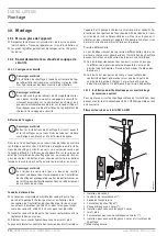
Страница 70: ... f f La longueur maximale admissible des conduits entre l ap pareil et la pompe à chaleur peut varier en fonction de la conception de l installation de chauffage pertes de charge Les valeurs indicatives sont de 10 m pour la longueur maxi male des conduits et de 22 à 28 mm pour leur diamètre f f Isolez les conduits de départ et de retour conformément à la réglementation en vigueur f f Réalisez les ...

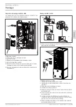
Страница 71: ...e raccordement Montage du HSBC 3 HKM 1 2 Nm D0000081576 f f Placez la vanne mélangeuse 3 voies à servomoteur dans la bonne position de montage D0000080376 7 8 10 Module tuyauterie installé 7 Isolation pour vanne mélangeuse 3 voies 8 Isolation pour vanne mélangeuse 3 voies et circulateur de chauffage 10 Pièces pour vanne mélangeuse 3 voies f f Installez le module tuyauterie f f Placez les joints pl...

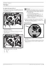
Страница 72: ...on Raccordement électrique Tension de commande 10 2 3 Si nécessaire monter le corps de chauffe additionnel HSBC 3 HE proposé comme accessoire D0000080386 2 1 1 Bride borgne 2 Élément isolant f f Retirez l élément isolant situé devant la bride f f Démontez la bride borgne 9 0 1 3 5 D0000080539 1 1 Contact de mise à la terre PE f f Placez le corps de chauffe additionnel dans la bonne position de mon...

Страница 73: ...ue Le corps de chauffe additionnel est fourni avec deux auto collants de schéma électrique identiques destinés à être collés à l emplacement HSBC 3 HE accessoire X2 11 du schéma électrique sur la face arrière du panneau avant dans cette notice voir chapitre Installation Don nées techniques Schéma électrique f f Après le montage du corps de chauffe additionnel collez un autocollant de schéma électr...

Страница 74: ...tre dé passée voir le chapitre Données techniques Tableau des données Dommages matériels Cet appareil doit être utilisé avec des robinetteries sans écoulement libre Conduit d eau froide Les matériaux autorisés sont l acier galvanisé l acier inoxydable le cuivre et les matières synthétiques Dommages matériels Une soupape de sécurité est requise Conduit d ECS boucle de circulation Les matériaux auto...

Страница 75: ...n voir le chapitre Données techniques Cotes et raccordements f f Raccordez la boucle de circulation 10 3 4 Raccordement de l eau froide et du groupe de sécurité f f Rincez soigneusement les conduits f f Installez le conduit de sortie d eau chaude sanitaire et le conduit d arrivée d eau froide voir le chapitre Données techniques Cotes et raccordements Réalisez les raccords hydrauliques avec des joi...

Страница 76: ...e du ballon d ECS f f Remplissez le ballon d eau chaude sanitaire par le raccord d arrivée d eau froide f f Ouvrez tous les robinets de soutirage placés en aval jusqu à ce que l appareil soit rempli et qu il n y ait plus d air dans les conduits f f Réglez le débit Notez le débit maximal admissible lorsque la robinetterie est ouverte au maximum voir le chapitre Données techniques Tableau des donnée...

Страница 77: ...re indicatif L installateur doit vérifier que ces sections correspondent aux be soins et répondent aux normes en vigueur Protection électrique Affectation Section de conducteur B 16 A Commande 1 5 mm 11 1 Tension de commande Dommages matériels f f Ne raccordez que des circulateurs haute efficacité énergétique agréés par nos services D0000080432 XD03 1 Borne de commande XD03 2 Borne de commande XD0...

Страница 78: ...corps de chauffe XD06 1 peut uniquement être utilisée en cas de montage du corps de chauffe ad ditionnel HSBC 3 HE D0000080434 XD06 1 Borne corps de chauffe accessoire HSBC 3 HE 11 4 Mise en place des sondes 11 4 1 Sonde de température pour le rafraîchissement option Pour le rafraîchissement il est nécessaire de poser une sonde de température disponible en accessoire f f Déposez le panneau avant v...

Страница 79: ...f f Si vous mettez l installation hors service placez le gestion naire de pompe à chaleur en veille de sorte que les fonctions de sécurité de l installation par ex protection hors gel restent actives 14 Maintenance AVERTISSEMENT Électrocution Exécutez tous les travaux de raccordement et d installa tion électriques conformément aux prescriptions AVERTISSEMENT Électrocution Avant toute intervention ...

Страница 80: ...593 10 20 d01 e02 d02 e01 c01 c10 c06 b01 D0000077428 HSBC 300 cool HSBC 300 L cool b01 Passage des câbles électriques c01 Arrivée eau froide Filetage mâle G 1 G 1 c06 Sortie eau chaude Filetage mâle G 1 G 1 c10 Boucle de circulation Filetage mâle G 1 2 G 1 2 d01 Départ PAC Diamètre mm 28 28 d02 Retour PAC Diamètre mm 28 28 e01 Départ chauffage Diamètre mm 22 22 e02 Retour chauffage Diamètre mm 22...

Страница 81: ...hauffage Diamètre mm 9 5 9 5 i01 Bride Diamètre extérieur Couple de serrage mm Nm 140 45 140 45 i18 Anode de protection Filetage femelle G 1 1 4 G 1 1 4 15 1 1 Accessoire HSBC 3 HKM 293 393 771 e31 e30 D0000080455 HSBC 3 HKM RBS SBC c01 Arrivée eau froide Diamètre mm 22 22 c06 Sortie eau chaude Diamètre mm 22 22 c10 Boucle de circulation Diamètre mm 12 12 e30 Départ chauffage circuit mélangé Diamè...

Страница 82: ...Puffer X1 4 T WW X1 8 T KUE X1 11 T MK X1 6 BT06 BT13 BT20 N 2 3 L 1 3 2 A B 1 KF 17 XD06 1 HSBC 3 HE Zubehör X2 11 L MA14 M 1 N MKP X2 4 6 1 2 5 3 3 4 2 N L HKP X2 3 2 MISCHER X2 14 N 2 L UV X2 8 1 4 5 3 6 2 N LA LZ 2 1 Vorderwand Front cover Deckelblech Top cover Netz 220 240V L M 1 N L M 1 N N 2 L 1 1 7 8 9 N L 10 1 2 PWM X1 16 XD04 9 XD06 2 BN PWM IN BU com BN PWM IN BU com MA15 3 N AB B AB A ...

Страница 83: ...ec HSBC 300 L cool et TSBC 300 L plus MA15 Moteur vanne d inversion chauffage ECS MA19 Moteur vanne mélangeuse circuit de chauffage 2 XD04 Borne de raccordement très basse tension XD06 1 Borne corps de chauffe accessoire HSBC 3 HE XD06 2 Borne corps de chauffe accessoire HSBC 3 HE XD03 1 Borne de commande circulateur PAC ballon tampon ECS XD03 2 Borne de commande circulateur hauffage circulateur c...

Страница 84: ...Installation Données techniques 84 HSBC 300 cool HSBC 300 L cool www stiebel eltron com 15 3 Schémas hydrauliques HSBC 300 cool D0000080569 HSBC 300 L cool D0000080571 D0000080570 ...

Страница 85: ...externe disponible circulateur circuit de chauffage 2 en option à 1 0 m h hPa 665 665 Différence de pression externe disponible circulateur circuit de chauffage 2 en option à 1 5 m h hPa 518 518 Différence de pression externe disponible circulateur circuit de chauffage 2 en option à 2 0 m h hPa 189 189 Limites d utilisation Pression maxi admissible ballon ECS MPa 1 0 1 0 Pression d essai ballon EC...

Страница 86: ...circulation mm 12 Versions Convient pour SBC 300 cool plus et 300 L cool plus Kit hydraulique HSBC 3 HKM HSBC 3 HKM 238825 Raccordements Raccordement circuit de chauffage mm 22 Corps de chauffe additionnel HSBC 3 HE HSBC 3 HE 200025 Données électriques Puissance de raccordement 230 V kW 2 Tension nominale V 230 Phases 1 N PE Fréquence Hz 50 Limites d utilisation Plage de réglage de la température ...

Страница 87: ...Une telle garantie ne pourra cependant être accordée que si la filiale a publié ses propres conditions de garantie Il ne sera accordé aucune garantie par ailleurs Nous n accordons aucune garantie pour les appareils achetés dans des pays où aucune filiale de notre société ne distribue nos produits D éventuelles garanties accordées par l importa teur restent inchangées Environnement et recyclage Mer...

Страница 88: ...tallatie Technische gege vens Gegevenstabel BIJZONDERE INFO BEDIENING 1 Algemene aanwijzingen 89 1 1 Geldende documenten 89 1 2 Veiligheidsaanwijzingen 89 1 3 Andere aandachtspunten in deze documentatie 89 1 4 Info op het toestel 89 1 5 Meeteenheden 89 2 Veiligheid 90 2 1 Reglementair gebruik 90 2 2 Algemene veiligheidsaanwijzingen 90 2 3 Keurmerk 90 3 Toestelcompatibiliteit 90 4 Toestelbeschrijvi...

Страница 89: ...e schok Verbranding verbranding verschroeiing 1 2 3 Trefwoorden TREFWOORD Betekenis GEVAAR Aanwijzingen die leiden tot zwaar letsel of overlijden wan neer deze niet in acht genomen worden WAARSCHUWING Aanwijzingen die kunnen leiden tot zwaar letsel of overlij den wanneer deze niet in acht genomen worden VOORZICHTIG Aanwijzingen die kunnen leiden tot middelmatig zwaar of licht letsel wanneer deze n...

Страница 90: ...g wordt onderbroken is de ac tieve vorstbescherming van de installatie niet meer ge garandeerd f f Onderbreek de stroomvoorziening ook buiten de verwarmingsperiode niet 2 3 Keurmerk Zie het typeplaatje op het toestel 3 Toestelcompatibiliteit U kunt het toestel in combinatie met de volgende lucht wa ter warmtepompen gebruiken HSBC 300 cool WPL 10 AC WPL 15 20 25 AC S WPL 19 24 I HSBC 300 L cool WPL...

Страница 91: ... Kalkaanslag Bijna al het water geeft kalk af bij hoge temperaturen De kalk slaat neer in het toestel en beïnvloedt de werking en de levens duur van het toestel De installateur die op de hoogte is van de plaatselijke waterkwaliteit kan u meedelen wanneer het volgende onderhoud uitgevoerd moet worden f f Controleer periodiek de kranen Verwijder kalk op de kraan uitlopen met in de handel verkrijgbar...

Страница 92: ...are drukoverschrij ding 8 2 2 Overig toebehoren Pompmodule voor een gemengd verwarmingscircuit HSBC 3 HKM Buiskit RBS SBC Extra verwarmingselement HSBC 3 HE Drukslangen Onthardingsarmatuur HZEA Temperatuursensor voor koeling Buiskit RBS SBC De hydraulische aansluitingen kunnen met de als toebehoren ver krijgbare buiskits RBS SBC achter de warmwaterboiler omhoog geleid worden 9 Voorbereidingen 9 1 ...

Страница 93: ...leverde 4 verstelbare voeten in het toestel f f Hef het toestel van de pallet Als smalle deuren of gangen de oplevering kunnen belemmeren kunt u het bovenste van het onderste deel van het toestel scheiden zoals in de volgende hoofdstukken is beschreven 9 2 1 Frontbekleding demonteren monteren D0000080283 f f Verwijder de 2 borgschroeven aan de bovenzijde van de frontkap f f Haak de frontbekleding ...

Страница 94: ...Installatie Voorbereidingen 94 HSBC 300 cool HSBC 300 L cool www stiebel eltron com 9 2 2 Overzicht isolatie elementen D0000080535 1 2 3 1 Isolatie element 1 2 Isolatie element 2 3 Isolatie element 3 ...

Страница 95: ...000080284 f f Verwijder isolatie element 1 f f Verwijder isolatie element 2 D0000080287 f f Trek de Sensor verwarming op het buffervat eruit D0000080288 f f Maak de sensorkabel uit de geleidingsgroef los D0000080289 f f Maak de steekverbinding van de 4 hydraulische aansluitingen los Trek daarvoor de veerklemmen met een schroevendraai er tot aan de aanslag eruit f f Trek de hydraulische aansluiting...

Страница 96: ...profielbalken er naar boven uit D0000080343 f f Maak de 4 schroeven los van de beugels vooraan op het toestel D0000074613 f f Trek het bovenste toesteldeel naar voren D0000080345 1 1 Griprail f f Kantel het bovenste toesteldeel naar achteren Gebruik de griprail voor een beter houvast D0000080347 f f Leg het bovenste toesteldeel op een ondergrond om bescha diging te voorkomen ...

Страница 97: ...et bovenste toesteldeel op de stippellijn op het on derste toesteldeel D0000074614 f f Schuif het bovenste toesteldeel naar achter totdat het gelijk komt met het onderste toesteldeel Wanneer u de toestelde len correct samenvoegt wordt de eindpositie door de gelei dingsgroef en de geleidingsbout bepaald f f Bevestig de beugels vooraan op het toestel f f Monteer de zijprofielbalken f f Monteer isola...

Страница 98: ...atie Voedingsleidingen f f Afhankelijk van de uitvoering van de verwarmingsinstallatie drukverliezen kan de maximaal toegelaten leidinglengte tussen het toestel en de warmtepomp variëren Als richt waarde moet worden uitgegaan van een maximale lei dinglengte van 10 m en een leidingdiameter van 22 28 mm f f Isoleer de aanvoer en retourleiding conform de regionale voorschriften f f Sluit de hydraulis...

Страница 99: ...gsnippels af terwijl u deze tegenhoudt Montage HSBC 3 HKM 1 2 Nm D0000081576 f f Breng de 3 weg mengklep met servomotor in de correcte inbouwpositie D0000080376 7 8 10 Buismodule geplaatst 7 Isolatiemat voor 3 weg mengklep 8 Isolatiemat voor 3 weg mengklep en circulatiepomp van het verwarmingscircuit 10 Gietstukken voor 3 weg mengklep f f Plaats de buismodule erin f f Plaats de vlakke afdichtingen...

Страница 100: ...risch aan zie hoofdstuk Installatie Elektrische aansluiting Stuurspanning 10 2 3 Monteer eventueel het toebehoren Extra verwarmingselement HSBC 3 HE D0000080386 2 1 1 Blindflens 2 Isolatie element f f Verwijder het isolatie element dat voor de flensplaat ligt f f Demonteer de blindflens 9 0 1 3 5 D0000080539 1 1 Aardingscontact PE f f Zet het extra verwarmingselement in de correcte inbouwpo sitie ...

Страница 101: ...ringsomvang van het extra verwarmingsele ment bevinden zich twee identieke schakelschemastic kers om over positie HSBC 3 HE toebehoren X2 11 in het elektriciteitsschema te plakken aan de achterzijde van de frontbekleding in deze handleiding zie hoofdstuk Installatie Technische gegevens Elektriciteitsschema f f Plak na de inbouw van het extra verwarmingsele ment telkens een schakelschemasticker op ...

Страница 102: ...ateriële schade De maximaal toegelaten druk mag niet worden over schreden zie hoofdstuk Technische gegevens Gege venstabel Materiële schade Het toestel dient met drukkranen gebruikt te worden Koudwaterleiding Als materiaal is thermisch verzinkt staal roestvast staal koper of kunststof toegestaan Materiële schade Een veiligheidsventiel is vereist Warmwaterleiding circulatieleiding Als materiaal is ...

Страница 103: ...ansluiting Circulatie zie Technische gegevens Afmetingen en aansluitingen f f Sluit de circulatieleiding aan 10 3 4 Drinkwateraansluiting en veiligheidsgroep f f Spoel de buizen grondig door f f Monteer de warmwateruitloopleiding en de koudwatertoe voerleiding zie hoofdstuk Technische gegevens Afmetin gen en aansluitingen Sluit de hydraulische aansluitingen met een vlakke afdichting aan f f Montee...

Страница 104: ...en f f Vul de warmwaterboiler via de aansluiting Koudwatertoevoer f f Open alle na het toestel geplaatste aftapkranen totdat het toestel gevuld is en het leidingnet luchtvrij is f f Stel het doorstroomvolume in Let daarbij op het maximaal toegelaten doorstroomvolume bij een volledig geopende kraan zie hoofdstuk Technische gegevens Gegevenstabel Reduceer zo nodig het doorstroomvolume op de smoring ...

Страница 105: ...ls aan overeenkomstig de volgende gegevens Het is uit het oogpunt van de beveiliging verplicht de volgende kabeldoorsnedes te installeren Zekering Toewijzing Kabeldiameter B 16 A Sturing 1 5 mm 11 1 Stuurspanning Materiële schade f f Sluit aan de pompaansluitingen alleen energiezuini ge circulatiepompen aan die door ons goedgekeurd zijn D0000080432 XD03 1 Aansluitklem sturing XD03 2 Aansluitklem s...

Страница 106: ...ng De aansluitklem verwarming XD06 1 kan alleen bij de inbouw van het optionele extra verwarmingselement HSBC 3 HE bezet worden D0000080434 XD06 1 Aansluitklem verwarming toebehoren HSBC 3 HE 11 4 Sensormontage 11 4 1 Eventueel toebehoren temperatuursensor bij koeling Bij koeling is de montage van een als toebehoren verkrijgbare temperatuursensor vereist f f Demonteer de frontbekleding zie hoofdst...

Страница 107: ...oiler aftappen f f Wanneer de installatie buiten werking wordt gesteld zet de warmtepompmanager dan op stand by zodat de veiligheids functies ter bescherming van de installatie bijv vorstbe scherming actief blijven 14 Onderhoud WAARSCHUWING elektrische schok Voer alle werkzaamheden voor elektriciteitsaansluitin gen en montage uit conform de voorschriften WAARSCHUWING elektrische schok Koppel alle ...

Страница 108: ...3 493 593 10 20 d01 e02 d02 e01 c01 c10 c06 b01 D0000077428 HSBC 300 cool HSBC 300 L cool b01 Doorvoer elektr kabels c01 Koudwatertoevoer Buitenschroefdraad G 1 G 1 c06 Warmwateruitloop Buitenschroefdraad G 1 G 1 c10 Circulatie Buitenschroefdraad G 1 2 G 1 2 d01 WP aanvoer Diameter mm 28 28 d02 WP retour Diameter mm 28 28 e01 Verwarming aanvoer Diameter mm 22 22 e02 Verwarming retour Diameter mm 2...

Страница 109: ...oneel Diameter mm 9 5 9 5 h53 Sensor verwarming Diameter mm 9 5 9 5 i01 Flens Buitendiameter Aandraaikoppel mm Nm 140 45 140 45 i18 Veiligheidsanode Binnendraad G 1 1 4 G 1 1 4 15 1 1 Toebehoren HSBC 3 HKM 293 393 771 e31 e30 D0000080455 HSBC 3 HKM RBS SBC c01 Koudwatertoevoer Diameter mm 22 22 c06 Warmwateruitloop Diameter mm 22 22 c10 Circulatie Diameter mm 12 12 e30 Aanvoer verw gemengd Diamete...

Страница 110: ...ffer X1 4 T WW X1 8 T KUE X1 11 T MK X1 6 BT06 BT13 BT20 N 2 3 L 1 3 2 A B 1 KF 17 XD06 1 HSBC 3 HE Zubehör X2 11 L MA14 M 1 N MKP X2 4 6 1 2 5 3 3 4 2 N L HKP X2 3 2 MISCHER X2 14 N 2 L UV X2 8 1 4 5 3 6 2 N LA LZ 2 1 Vorderwand Front cover Deckelblech Top cover Netz 220 240V L M 1 N L M 1 N N 2 L 1 1 7 8 9 N L 10 1 2 PWM X1 16 XD04 9 XD06 2 BN PWM IN BU com BN PWM IN BU com MA15 3 N AB B AB A 2 ...

Страница 111: ... aanwezig bij HSBC 300 L cool en TSBC 300 L plus MA15 Motor omschakelklep verwarming WW MA19 Motor mengklep verwarmingscircuit 2 XD04 Aansluitklem laagspanning XD06 1 Aansluitklem verwarming toebehoren HSBC 3 HE XD06 2 Aansluitklem verwarming toebehoren HSBC 3 HE XD03 1 Aansluitklem besturing netwerk bufferlaadpomp XD03 2 Aansluitklem besturing verwarmingscircuitpomp pomp verwarmingscircuit 2 XD03...

Страница 112: ...Installatie Technische gegevens 112 HSBC 300 cool HSBC 300 L cool www stiebel eltron com 15 3 Hydraulische schakelschema s HSBC 300 cool D0000080569 HSBC 300 L cool D0000080571 D0000080570 ...

Страница 113: ...2 0 m h hPa 444 444 Extern beschikbaar drukverschil circulatiepomp verwarmingscircuit 2 optioneel bij 1 0 m h hPa 665 665 Extern beschikbaar drukverschil circulatiepomp verwarmingscircuit 2 optioneel bij 1 5 m h hPa 518 518 Extern beschikbaar drukverschil circulatiepomp verwarmingscircuit 2 optioneel bij 2 0 m h hPa 189 189 Werkingsgebied Max toegelaten druk warmwaterboiler MPa 1 0 1 0 Testdruk wa...

Страница 114: ...er mm 22 Aansluiting circulatie leiding mm 12 Uitvoeringen Geschikt voor SBC 300 cool plus en 300 L cool plus Pompmodule HSBC 3 HKM HSBC 3 HKM 238825 Aansluitingen Aansluiting verwarmingscircuit mm 22 Extra verwarmingselement HSBC 3 HE HSBC 3 HE 200025 Aansluitvermogen 230 V kW 2 Nominale spanning V 230 Fasen 1 N PE Frequentie Hz 50 Frequentie Hz 50 Werkingsgebied Temperatuurinstelbereik C 35 80 M...

Страница 115: ...r deze doch termaatschappij Een dergelijk garantie wordt alleen verstrekt wanneer de dochtermaatschappij eigen garantievoorwaarden heeft gepubliceerd In andere situaties wordt er geen garantie verleend Voor toestellen die in landen worden gekocht waar wij geen dochtermaatschappijenhebbendieonzeproductenverkopen verlenen wij geen garantie Een eventueel door de importeur verzekerde garantie blijft o...

Страница 116: ... Dati tecni ci Tabella dei dati AVVERTENZE SPECIALI USO 1 Avvertenze generali 117 1 1 Documenti di riferimento 117 1 2 Avvertenze di sicurezza 117 1 3 Altre segnalazioni utilizzate in questo documento 117 1 4 Avvertenze riportate sull apparecchio 117 1 5 Unità di misura 117 2 Sicurezza 118 2 1 Uso conforme 118 2 2 Istruzioni di sicurezza generali 118 2 3 Marchio di collaudo 118 3 Compatibilità del...

Страница 117: ...one Scarica elettrica Ustione ustione scottatura 1 2 3 Termini di segnalazione TERMINE SE GNALAZIONE Significato PERICOLO Indicazioni che se non osservate causano lesioni gravi o addirittura letali AVVERTENZA Indicazioni che se non osservate possono causare lesioni gravi o addirittura letali CAUTELA Indicazioni che se non osservate possono causare lesioni medio gravi o lievi 1 3 Altre segnalazioni...

Страница 118: ...l alimentazione di tensione nem meno fuori del periodo stagionale di riscaldamento 2 3 Marchio di collaudo Vedere la targhetta di identificazione dell apparecchio 3 Compatibilità dell apparecchio L apparecchio può essere utilizzato in combinazione con le se guenti pompe di calore aria acqua HSBC 300 cool WPL 10 AC WPL 15 20 25 AC S WPL 19 24 I HSBC 300 L cool WPL 09 17 ICS IKCS classic WPL 19 24 I...

Страница 119: ...crostazioni calcaree Queste si depositano nell appa recchio e influenzano il funzionamento e la vita utile di servizio dell apparecchio stesso Il tecnico specializzato che conosce la qualità dell acqua locale potrà comunicare l intervallo per la ma nutenzione successiva f f Controllare regolarmente i rubinetti Le incrostazioni calcaree sulle uscite dei rubinetti si rimuovono con prodotti anticalca...

Страница 120: ...ori Gruppo pompa per un circuito di riscaldamento misto HSBC 3 HKM Set tubi RBS SBC Elemento riscaldante supplementare HSBC 3 HE Tubi a pressione Rubinetto addolcitore HZEA Sensore temperatura per raffrescamento Set tubi RBS SBC Gli allacciamenti idraulici possono essere effettuati verso l alto dietro l accumulatore dell acqua calda sanitaria utilizzando il set di tubi RBS SBC disponibile come acc...

Страница 121: ...golabili forniti in dotazione f f Sollevare l apparecchio dal pallet Se porte o corridoi stretti impediscono la movimentazione è possibile separare la parte superiore dell apparecchio da quella inferiore come descritto nel prossimo capitolo 9 2 1 Smontaggio Montaggio del rivestimento anteriore D0000080283 f f Rimuovere le 2 viti di fermo sul lato superiore del rivesti mento frontale f f Sganciare ...

Страница 122: ...llazione Operazioni preliminari 122 HSBC 300 cool HSBC 300 L cool www stiebel eltron com 9 2 2 Panoramica elementi isolanti D0000080535 1 2 3 1 Elemento isolante 1 2 Elemento isolante 2 3 Elemento isolante 3 ...

Страница 123: ...izzare come maniglie D0000080284 f f Rimuovere l elemento isolante 1 f f Rimuovere l elemento isolante 2 D0000080287 f f Sfilare il Sensore riscaldamento dal serbatoio tampone D0000080288 f f Staccare il cavo del sensore dalla scanalatura di guida D0000080289 f f Allentare i connettori sfilabili dei 4 allacciamenti idraulici A tale scopo sfilare i morsetti elastici con un cacciavite fino all arres...

Страница 124: ...so l alto D0000080343 f f Allentare le 4 viti delle linguette sul davanti dell apparecchio D0000074613 f f Tirare la parte superiore dell apparecchio in avanti D0000080345 1 1 Listello impugnatura f f Inclinare la parte superiore dell apparecchio all indietro Uti lizzare il listello impugnatura per una presa migliore D0000080347 f f Posare la parte superiore dell apparecchio su una base di appoggi...

Страница 125: ... la parte superiore dell apparecchio in corri spondenza della linea tratteggiata sulla parte inferiore dell apparecchio D0000074614 f f Spingere indietro la parte superiore dell apparecchio fino a portarla a filo con la parte inferiore Se le parti dell appa recchio sono assemblate correttamente la posizione finale è predeterminata dalla scanalatura e dal perno di guida f f Fissare le linguette sul...

Страница 126: ...to Tubazioni di alimentazione f f La lunghezza massima consentita delle tubazioni tra appa recchio e pompa di calore può variare in funzione del tipo di sistema di riscaldamento perdite di pressione Assumere come valore di riferimento per le tubazioni una lunghezza massima di 10 m e un diametro di 22 28 mm f f Isolare la linea di mandata e quella di ritorno come da nor mative locali f f Collegare ...

Страница 127: ...circuito di riscaldamento f f Tenendoli bloccati svitare i tappi ciechi dai nippli di raccordo Montaggio di HSBC 3 HKM 1 2 Nm D0000081576 f f Portare il miscelatore a 3 vie con servomotore nella corretta posizione di montaggio D0000080376 7 8 10 Gruppo tubi inserito 7 Tappetino isolante per miscelatore a 3 vie 8 Tappetino isolante per miscelatore a 3 vie e pompa di circola zione del circuito di ri...

Страница 128: ...apitolo Installazione Allacciamento elettrico Tensione di comando 10 2 3 Eventuale montaggio dell accessorio elemento riscaldante supplementare HSBC 3 HE D0000080386 2 1 1 Flangia cieca 2 Elemento isolante f f Rimuovere l elemento isolante che si trova davanti alla pia stra flangiata f f Smontare la flangia cieca 9 0 1 3 5 D0000080539 1 1 Contatto di terra PE f f Portare l elemento riscaldante sup...

Страница 129: ...te supplementare sono inclusi due adesivi identici con lo schermo elettrico gli adesivi devono essere incollati con riferimento alla posizione HSBC 3 HE accessorio X2 11 nello schema elettrico sul retro del rivestimento frontale in queste istruzioni vedere capitolo Installazione Dati tecnici Schema elettrico f f Dopo aver montato l elemento riscaldante supple mentare incollare un adesivo con lo sc...

Страница 130: ...teriali Non superare la pressione massima ammessa vedere capitolo Dati tecnici Tabella dei dati Danni materiali L apparecchio deve essere utilizzato con accessori idrau lici per l utilizzo sotto pressione Tubazione acqua fredda Sono ammessi i seguenti materiali acciaio zincato acciaio inox rame e plastica Danni materiali È necessaria una valvola di sicurezza Tubazione acqua calda linea di circolaz...

Страница 131: ...one DHW vedere il capitolo Dati tecnici Misure e allacciamenti f f Allacciare la linea di circolazione DHW 10 3 4 Allaccio acqua potabile e gruppo di sicurezza f f Sciacquare bene le tubazioni f f Montare la tubazione di uscita dell acqua calda e quella di adduzione dell acqua fredda vedere il capitolo Dati tecnici Misure e allacciamenti Collegare gli allacci idraulici con guarnizioni piatte f f I...

Страница 132: ...calda sanitaria tramite l allaccio Acqua fredda mandata f f Aprire tutte le valvole di prelievo collegate a valle quanto basta per riempire l apparecchio e togliere completamente l aria dalla rete delle tubazioni f f Regolare la portata Eseguire questa operazione attenendosi alla portata massima ammissibile con la rubinetteria com pletamente aperta vedere il capitolo Dati tecnici Tabella dei dati ...

Страница 133: ...stallare cavi con le seguenti sezioni concordemente al dimen sionamento del fusibile Fusibile Assegnazione Sezione cavo B 16 A Comando 1 5 mm 11 1 Tensione di comando Danni materiali f f Collegare agli allacciamenti della pompa solo pompe di circolazione ad alta efficienza da noi omologate D0000080432 XD03 1 Allacciamento comandi XD03 2 Allacciamento comandi XD03 3 Allacciamento comandi XE03 Morse...

Страница 134: ...ldamento XD06 1 può essere asse gnato solo in caso di montaggio dell elemento riscaldante opzionale HSBC 3 HE D0000080434 XD06 1 Morsetto riscaldamento accessorio HSBC 3 HE 11 4 Installazione dei sensori 11 4 1 Eventuale sensore di temperatura come accessorio per raffrescamento Per il raffrescamento è necessario montare un sensore di tempe ratura disponibile come accessorio f f Smontare il rivesti...

Страница 135: ... f f Quando si spegne l impianto regolare il quadretto di coman do su Standby in modo che le funzioni di sicurezza per la protezione dell impianto ad es antigelo restino attive 14 Manutenzione AVVERTENZA Scarica elettrica Eseguire tutti i lavori di collegamento elettrico e di in stallazione come da normativa AVVERTENZA Scarica elettrica Prima di eseguire qualsiasi intervento sull apparecchio stacc...

Страница 136: ...02 d02 e01 c01 c10 c06 b01 D0000077428 HSBC 300 cool HSBC 300 L cool b01 Passaggio cavi elettrici c01 Acqua fredda mandata Filettatura esterna G 1 G 1 c06 Acqua calda uscita Filettatura esterna G 1 G 1 c10 Circolazione DHW Filettatura esterna G 1 2 G 1 2 d01 PC mandata Diametro mm 28 28 d02 PC ritorno Diametro mm 28 28 e01 Riscaldamento mandata Diametro mm 22 22 e02 Riscaldamento ritorno Diametro ...

Страница 137: ...h53 Sensore riscaldamento Diametro mm 9 5 9 5 i01 Flangia Diametro esterno Coppia di serraggio mm Nm 140 45 140 45 i18 Anodo di protezione Filettatura femmina G 1 1 4 G 1 1 4 15 1 1 Accessorio HSBC 3 HKM 293 393 771 e31 e30 D0000080455 HSBC 3 HKM RBS SBC c01 Acqua fredda mandata Diametro mm 22 22 c06 Acqua calda uscita Diametro mm 22 22 c10 Circolazione DHW Diametro mm 12 12 e30 Mandata riscaldame...

Страница 138: ...fer X1 4 T WW X1 8 T KUE X1 11 T MK X1 6 BT06 BT13 BT20 N 2 3 L 1 3 2 A B 1 KF 17 XD06 1 HSBC 3 HE Zubehör X2 11 L MA14 M 1 N MKP X2 4 6 1 2 5 3 3 4 2 N L HKP X2 3 2 MISCHER X2 14 N 2 L UV X2 8 1 4 5 3 6 2 N LA LZ 2 1 Vorderwand Front cover Deckelblech Top cover Netz 220 240V L M 1 N L M 1 N N 2 L 1 1 7 8 9 N L 10 1 2 PWM X1 16 XD04 9 XD06 2 BN PWM IN BU com BN PWM IN BU com MA15 3 N AB B AB A 2 1...

Страница 139: ... 300 L plus MA15 Motore valvola di commutazione riscaldamento ACS MA19 Motore valvola miscelatore circuito di riscaldamento 2 XD04 Morsettiera bassa tensione XD06 1 Morsetto riscaldamento accessorio HSBC 3 HE XD06 2 Morsetto riscaldamento accessorio HSBC 3 HE XD03 1 Allacciamento comandi pompa di carico tampone di rete XD03 2 Allacciamento comandi pompa circuito di riscaldamento pompa circuito di ...

Страница 140: ...Installazione Dati tecnici 140 HSBC 300 cool HSBC 300 L cool www stiebel eltron com 15 3 Schemi idraulici HSBC 300 cool D0000080569 HSBC 300 L cool D0000080571 D0000080570 ...

Страница 141: ...amento 1 a 2 0 m h hPa 444 444 Pressione differenziale esterna disponibile tra pompa di circolazione e circuito di riscaldamento 2 opzionale a 1 0 m h hPa 665 665 Pressione differenziale esterna disponibile tra pompa di circolazione e circuito di riscaldamento 2 opzionale a 1 5 m h hPa 518 518 Pressione differenziale esterna disponibile tra pompa di circolazione e circuito di riscaldamento 2 opzio...

Страница 142: ...fredda mm 22 Allacciamento acqua calda mm 22 Attacco circolazione DHW mm 12 Versioni Idoneo per SBC 300 cool plus e 300 L cool plus Gruppo pompa HSBC 3 HKM HSBC 3 HKM 238825 Allacciamenti Collegamento circuito di riscaldamento mm 22 Elemento riscaldante supplementare HSBC 3 HE HSBC 3 HE 200025 Dati elettrici Carico connesso 230 V kW 2 Tensione di alimentazione V 230 Fasi 1 N PE Frequenza Hz 50 Lim...

Страница 143: ...ata solo da tale affiliata Questa garanzia può essere prestata solo se l affiliata ha rilasciato condizioni di garanzia proprie Per quant altro non viene prestata alcuna garanzia Non prestiamo alcuna garanzia per apparecchi acquistati in paesi in cui nessuna delle nostre affiliate distribuisce i nostri prodotti Restano invariate eventuali garanzie prestate dall im portatore Ambiente e riciclaggio ...

Страница 144: ...tron cz www stiebel eltron cz Finland STIEBEL ELTRON OY Kapinakuja 1 04600 Mäntsälä Tel 020 720 9988 info stiebel eltron fi www stiebel eltron fi France STIEBEL ELTRON SAS 7 9 rue des Selliers B P 85107 57073 Metz Cédex 3 Tel 0387 7438 88 Fax 0387 7468 26 info stiebel eltron fr www stiebel eltron fr Hungary STIEBEL ELTRON Kft Gyár u 2 2040 Budaörs Tel 01 250 6055 Fax 01 368 8097 info stiebel eltro...

Отзывы: