16
17
SET TInGS AdjUSTmEnT
BATTERy REPLAcEmEnT
BATTeRy MODeLS OnLy
When the battery weakens, the red indicator light will blink at a constant rate when
the user’s hands are within the sensor range. The battery must be replaced within two
weeks.
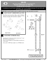
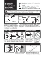
TO RePLACe THe BATTeRy:
1. For Tubular
1000
B: Carefully open the battery box and remove the old batteries.
Replace the used batteries with six new
1.5
V AA batteries. Close the box.
2. For Tubular 1000 B Box: Release the screws at the panel and remove it. The battery
box is located behind the panel. Carefully open the battery box and replace the used
battery with a new 9V battery (Lithium battery is recommended). Close the box and
re-assemble the wall cover panel.
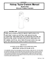
iMPORTAnT:
These models were supplied with a self adjusting sensor.
The ideal sensor range for the specific location will be set automatically again after
changing the battery.
15
SECONDS
ABOUT
OBJECT
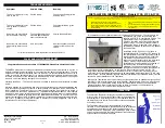
After you have replaced the battery,
move away from the sensor range. Wait
15
seconds in order to allow the system
to set the ideal sensor range. Then after
the self adjustment has taken place the
solenoid valve will be opened and closed
for 1 second as an indication that the ideal
sensor range was set and the product is
ready for use.
Check that there are no objects in front of
the sensor after the battery replacement
was completed.
iMPORTAnT
: Spent batteries should not be disposed of with normal
household waste. Contact your local authority for information on waste
disposal and recycling.
DELAY IN TIME: It is recommended to change the delay in time for
flush valves for urinals or toilets only.
If required, the delay in time can also be modified in faucets as
follows:
Press the IN button. Wait until a quick flashing of the red light in
the sensor eye is perceived. Then, press + to increase the delay in
time and – to reduce it.
DELAY OUT TIME: This button allows modifying the water flow
time after the user removes his hands from the faucet. A delay out
time close to 0 will save more water. An increased delay out time
will make the user experience more comfortable.
If required, the delay out time can be modified as follows:
Press the OUT button. Wait until a quick flashing of the red light
in the sensor eye is perceived. Then, press + to increase the delay
out time and – to reduce it.
24 HOUR HYGIENE FLUSH: This model includes a 24 hours hygiene
flush which is disabled. To activate the hygiene flush, press the
clock button. Wait until a quick flashing of the red light in the
sensor eye is perceived. Then press + to activate the hygiene flush.
To disable it again, press – to deactivate it.
COMFORT FLUSH: If your model includes a Comfort flush setting, it
can be activated by pressing the flush button.
When the button is pressed, one blink of the blue light in the
sensor eye is perceived. The pre-programmed flush cycle will take
place then.
The Comfort flush cannot be interrupted or deactivated by pressing
any button until it is over.
TEMPORARY OFF FUNCTION: This function is ideal to perform any
kind of activity in front of the sensor without operating the system
(for example, cleaning).
The faucet will remain shut for 1 minute when this button is
pressed once. To cancel this function and to return to normal
operation press the On/Off button again or wait 1 minute.
RESET BUTTON: This function restores all the factory settings
except for the sensor range. If required, press the Reset button
and without releasing it, press the + button once.
nOTe:
To enter the self adjusting mode, use the ADJ button. To change the sensor
range, use the RANGE button.