Maintenance Manual STEMME S10-VT
Date of Issue: Jan. 01, 1998
Page 7-19
Amendment Nr. 8
Date: Nov. 11, 1999
A4011121_B23.doc
Doc. No. A40-11-121
7.4.10 Propeller
System description
See section 3.4.10
The numerical positions in the following text refer to the propeller diagram (see figure 3.4.10 a).
7.4.10.1 General:
The complete propeller pitch control mechanism (including all mechanical and electrical components) is
double redundant and is able to operate each propeller blade separately. Both systems are coupled to each
other through a mechanical coupling ring and an electrical backup system. The mechanism hence is fully
redundant.
In order to prevent incorrect assembly, all paired parts belonging to the pitch variation of
the one propeller blade are marked with a red dot
, those belonging to the other blade remain unmarked.
Propeller pitch can be changed manually for inspection and maintenance purposes by swinging the blades
approx. 90 outward, gripping the blades in the outer third of their length and pressing them in the direction of
flight (fine pitch) or against direction of flight (course pitch). See also details in Flight Manual S10-VT,
Section 4, Daily Checks.
Adjustment of the propeller or its electric system may only be performed by the manufacturer or by qualified
and authorised personnel. All results of an inspection of the adjustment or changes in setting must be
entered in a report according to Form "Propeller Adjustment Report" (Annex D). The last valid report must be
filed together with the Operational Documentation (Annex C).
Repair, overhaul and inspection of structural damage to the variable pitch propeller or to its subsidiary
assemblies after an operational interruption may only be performed by the manufacturer or by a facility
authorised by the manufacturer.
Balancing the variable pitch propeller or its assemblies may only be performed by the manufacturer
or by an authorised and licensed FBO according to the specific instructions and using appropriate
equipment.
Balancing weights have to be applied for static or dynamic balancing. Their arrangement must
be entered in the Rigging Report as laid down in the “Propeller Rigging Report” form (Annex D) or
A17-10AP-V/2-E (Annex A) .
In the case of damage of one propeller blade only, a suitable exchange blade may possibly be obtained from
the manufacturer. The latest Report of Adjustment Settings must be transmitted to the manufacturer and in
this case, re-balancing may not be necessary.
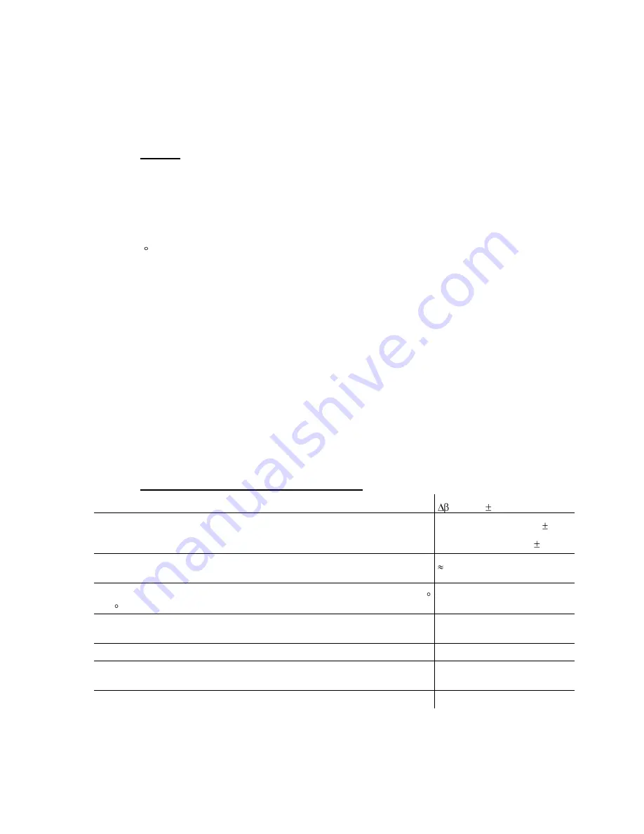
7.4.10.2 Adjustment and Inspection Results, Tolerances
Changes in pitch angle:
= 6°
24’
15'
Settings, measurement taken at the propeller blade mounting fork with
reference to zero setting (this is when the axis of the joint is parallel to the
propeller axis of rotation.
Take-Off setting: -2°
30’
5'
Cruise setting: +3°
54’
10'
Initial tension of the contact spring for the take-off position stop switch
0.2 mm / 0.0079 in.
(
1
/
3
turn of the contact screw)
Duration of pitch change in each direction at an ambient temperature of 15
- 25 C and battery voltage of not less than 12 V under loaded conditions
max. 3 Min.
Unbalance:
Permissible total static residual unbalance
Permissible dynamic unbalance
200 g mm / 44.4 dr. in.
see A17-10AP-V/2-E
Permissible travel of the blade tips in the direction of flight
4 mm / 0.16 in.
Track at propeller blade joint (difference between both forks, measurement
taken opposite the position ‘upper left gear mount’)
0.3 mm / .012 in.
Track at propeller blade tips (difference between both blades)
3 mm / 0.12 in.


