I N S T A L L A T I O N
Installation – step 6
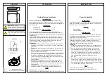
Control installation
General guidelines for control installation
It is a good prac ce to install the following safety controls:
An air proving switch (APS) in the same duct as the humidifier’s steam ramp so that it
can prevent humidifier from producing steam in case there is no air flow.
A high limit humidistat shall be installed downstream of the steam ramp so that it can
prevent any over humidity (condensing) occurrence. High limit humidistat is usually
provided by an on-off switch its set point should be 85%RH minimum.
High limit humidistat should be placed at least at a distance equivalent to five mes
the absorp on distance. If the absorp on distance is not known, locate it at least 9
feet (3m) downstream of the steam ramp.
For system that needs very accurate RH% control a RH% sensor can replace or
supplement the On/Off Hi Limit humidistat in this case the IER will not only modulate
the steam produc on based on the control; signal demand but also on this
propor onal Hi-Limit signal.
An enable dry contact can also be wired to switch the humidifier ON or OFF, this
enable contact can be used either as a third safety control or as a way to control the
humidifier ON and OFF, although IER steam humidifier is fully modula ng.
Alarm
contact
Oper.
contact
H
i l
im
it
RH
%
s
w
itc
h
Ai
r p
ro
vi
ng
s
w
itc
h
24VAC-2
Hi Limit
switch
Enable
Contact
Air Flow
Switch
Analog
input
RH analog
input
O
p
on
al
E
na
bl
e
co
nt
ac
t
O
p
on
al
o
ut
si
de
p
ow
er
s
ou
rc
e
fo
r H
i L
im
it
O
p
on
al
o
ut
sid
e
po
w
er
s
ou
rc
e
fo
r e
na
bl
e
co
nt
ac
t
O
p
on
al
o
ut
si
de
p
ow
er
so
ur
ce
fo
r A
PS
Ex
te
rn
al
a
na
lo
g
si
gn
al
fo
r d
em
an
d
or
ex
te
rn
al
s
et
po
in
t s
ig
na
l
24
Va
c
ou
tp
ut
–
2
A
m
ax
24
Va
c
G
nd
RH
%
s
ig
na
l
RH%
sensor
or Temp.
sensor
RS485
A
B
IER main controller
Op onal BACnet
or Modbus signal
Steam On
NC & NO contacts
Alarm
NC & NO contacts
Figure 34 – Control connec on
29