ENGLISH
24
24
2.3.-EMF Information
To reduce magnetic fields in the workplace, use the
followingprocedures:
1.Keep cables close together by twisting or taping them, or using
acable cover.
2.Arrange cables to one side and away from the operator.
3.Do not coil or drape cables around your body.
4.Keep welding power source and cables as far away from
operator as practical.
5.Connect work clamp to workpiece as close to the weld as
possible.
Warning:
In fire and electrical shock increment risk
places as close to flammable and explosive stuff, height,
reduced freedom of movement, physical contact with
conductors, hot ambiences that reduces electrical
resistance of human skin and devices please compulsory
observe the local and national legal regulations.
3. - Startup instructions
3.1.-Placement
The machine must be placed in a dry, ventilated area and at a
distance of at least 15 cm away from any wall. The equipment
may skid on surfaces with inclinations of more than 3O so that ii
must always compulsorily be placed on an even and dry surface.
For placement on surfaces having a higher slope, please secure
the machine with chains or belts.
3.2.- Mounting
The equipment must be mounted respecting its environmental
limits and placing it adequately.
The equipment will be installed according to the requirements
indicated on the rating plate of the equipment.
3.3.- Connection to the grid
The equipment is powered by means of the series-provided
cable and connector through a differential switch and a connector
slowfeature electromagnet of an electrical strength according
to the table of technical features. Any connection must have
a regulatory connection to earth and comply with all domestic
regulations on electricity.
Offline Use spaces to regulatory ground.
In the case of a connection to an electric generator, the power
needs as indicated in the technical features are to be observed.
It must be taken into account that an equipment can operate with
a generator with a power that is lower than the indicated one
with the limitation that it is to be used at a maximum electrical
strength that is lower than the nominal one.
Model BITENSIÓN 20/14 is able to work in the range of power
supply voltage 100V to 240V, 50Hz-400Hz.
The computer automatically detects the input voltage and
configures itself.
3.4.- Limitation of environmental conditions
The equipment must be installed respecting the IP21
classification thereof; this means that the equipment is protected
at the most against the vertical fall of water drops and access to
dangerous parts with a finger and against solid bodies of 12.5
mm and larger ones.
The equipment is prepared for working within the temperature
range of -15ºC to 70ºC, taking into account the limitation of its
drop in performance (duty cycle) as of temperatures higher than
40ºC.
4.- Operating instructions
4.1.- Placement and tests
All
STAYER WELDING
machines of the MMA series must
be handled by means of the belt handle which is enabled for
transport. A free space of at least 15 cm must be provided around
the equipment, and free circulation of air must be secured for a
correct heat dissipation.
Before each work, the good status and correct tightening of
each of the external elements of the equipment must be verified:
power supply plug, cable, carpentry of the casing and connection
terminals and switches.
4.2.- Changing tools
All
STAYER WELDING
machines of the MMAseries have a
DINSE half-inch or 3/8 inch quick connector for the welding
cables. For removing or putting the connector it is sufficient to
turn the connector a fourth of a turn leftward or rightward.
ATTENTION: Always turn the DINSE connector to the limit and
make sure that the junction with the cable is in a good status and
that the contact surface is clean. Abad junction or a dirty junction
lead to a bad yield and will cause the front panel to heat up, fuse
or burn.
4.3.- Adjusting operations
All
STAYER WELDING
machines of contain a complex
electronic system and are provided ex works in a completely
calibrated status, so that the user is not authorized to manipulate
it for reasons of efficiency and safety. In the case of any doubt
concerning bad functioning please contact your dealer or our
customer service system.
4.4.- Limits of the size of the work piece
The main restriction on the size of the piece to be welded is the
thickness thereof that it limited by the power of the equipment.
The higher power is, you will be able to make correct welds (with
an adequate penetration of the weld bead) in pieces of major
thickness. The following table may serve as an orientation.
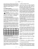
THICKNESS OF THE
PIECE TO BE WELDED
ELECTRODE
DIAMETER E6013
AMPERAGE
ADJUSTING RANGE
1 a 2 mm
1,6mm
30 - 60
1,5 a 3mm
2,0mm
50 - 70
2,5 a 5mm
2,5mm
60 - 100
5 a 8mm
3,2mm
85 - 140
8 a 12mm
4,0mm
120 - 190
More than 12mm
5,0 - 6,0mm
180 - 350
4.5.- General instructions for use
Before starting, make sure that you read, understand and apply
the safety instructions and the rest of the instructions included in
the present manual.
Hereinafter you will find a series of general indications that will
allow you to initiate yourself in the world of welding and to start
to work efficiently.
Содержание BITENSION 20/14
Страница 3: ...3 3 fig 9 POTENZA TIG 170 HF 3 12 11 10 5 8 5 1 7 2 6 ...
Страница 52: ...POLSKI 52 52 ...


