background image

49 of 222 pages

Operating and service manual

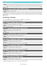
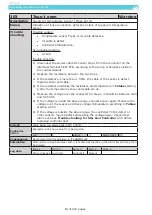
F09  Serial number of controller board (Main PCB)

Function:

Shows the serial number of the controller board

 Value:

°C and °F Temperature Scale Showing, Alternately 

As long as the button      is pressed, °F is shown instead of °C and PSI is shown instead of Bar. 

When the button is released, °C and Bar is shown again.

Permanently change to °F/PSI is not available.

Shown pressure is relative to atmosphere pressure.

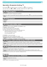
Viewing graph of Supply and Return Temperature   

Press 

 to enter graphical view (this function is a shortcut to L03 (see “Datalog view:” p. 46)).

To return to main page press 

 two times.

Press 

 to toggle between stored set of temperatures: Setpoint tempe supply air tem-

perature, return air temperature and the other set of temperatures: USDA 1 + 2 + 3 temperatures 

and cargo temperature.
Press up 

 or 

 down, , to show newer or older stored set of values from the data log.

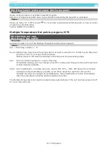
Manual Defrost Initiation 

A manual defrost is only accepted if Tevap less than (<) 15°C (59°F)
Defrosting is manually initiated by pressing the 

 key and holding it for 3 sec. The display shows 

the 

  icon as an acceptance of defrost initiation.

A automatically or manually initiated defrosting may be terminated by pressing 

 and holding it 

for 3 sec. The display will cancel the 

 icon.

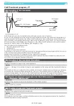
Water-cooling Activation/Deactivation   

The following only applies for Model SC-MCI40-WC 

Water-cooling connecting is executed as follows:

• 

The container must be connected to the water-cooling system.

• 

Press 

 and hold it for 3 sec. The display shows the  icon as an acceptance of water-cooling  

operation. The condenser fan is deactivated.

Water-cooling turn-off is executed as follows:

• 

Press 


and hold it for 3 sec. The display turns off the 

 icon as an acceptance of non-op- 

erating water- cooling. The condenser fan turns on automatically.

• 

The container can be disconnected from the water-cooling system.

If the water supply is insufficient (the water hose is jammed, the water is not running or the 

water temperature is too high), the temperature in the condenser will rise and cooling capacity 

is decreasing and thereby threatening the cargo. If the condenser temperature rises above 58˚C 

(136˚F), the system will automatically switch to air-cooling of condenser by turning the condenser 

fan on. If the water flow is restored, the controller stops air-cooling of the condenser. If the tem

-

perature stays at the high temperature for more than 1 hour, an alarm is given. The actual setting 

of water-cooling is remembered if the unit is switched off or there should be a power loss.

Water-cooling is only turned off when the set point temperature is changed or when water-cooling 

is turned off manually.

Содержание 810200B

Страница 1: ...ment is available 24 hours a day 7 days a week providing easy access to the answers you need For further troubleshooting help go to our website URL m starcool com or simply scan the QR code with Your smartphone Bjerndrupvej 47 6360 Tinglev Denmark Phone 45 73 64 34 00 Fax 45 73 64 35 69 E mail starcool starcool com www starcool com Copyright Maersk Container Industry AS Operating and service manua...

Страница 2: ...l you have familiarized yourself completely with the equipment and operating of this unit by reading the instruction in this manual Do not perform any welding on the unit before disconnecting the power plug Disconnect main power supply to unit before inspecting the interior of the con troller box The unit is charged with R134a and ester oil BSE 55 Do not use any other refrig erant or oil Do not us...

Страница 3: ...trol 18 Expansion valve control 18 Condenser fan control 18 Dehumidification control 19 Defrost control 19 Electrical control 19 Refrigeration system data 20 Refrigerant charge R134a 20 General specification 20 Compressor motor assembly 21 Frequency converter FC 21 High Pressure cut out switch 21 Fusible plug receiver 21 Economizer 21 Evaporator coil 21 Condenser coil 21 Evaporator fan 22 Condense...

Страница 4: ... points program MTS 41 Cold Treatment program CT 42 Alarms 43 Service Function Setting Viewing 44 Manual operations 45 Datalog view 46 Time adjust 46 Run time counters 47 Configuration 48 Serial Numbers 49 C and F Temperature Scale Showing Alternately 49 Viewing graph of Supply and Return Temperature 49 Manual Defrost Initiation 49 Water cooling Activation Deactivation 49 Emergency Operation 50 Ex...

Страница 5: ...of compressor 194 Replacement of compressor valve plate cylinder head gasket 195 Service and maintenance 196 Evacuation of refrigerant 196 Compressor pump down operation 197 Compressor pump down replaced 197 Pump down of unit 198 Pressure Test 198 Charging of refrigerant 199 Charging of an empty unit 199 Charging of unit low on charge 199 Leakage detection 200 Fan motors 200 Drying filter 201 Repl...

Страница 6: ...ow pressure transmitter NSK 213 Voltage Pressure Table High pressure transmitter AKS 214 Voltage Pressure Table High pressure transmitter NSK 215 Temperature Sensor Voltage Table 216 Tightening torques 217 P I diagram 218 Controller Unit Illustration 219 Star Cool Unit installation dimensions 220 Overall Wiring Schematic 222 ...

Страница 7: ...verheat Mevap2OH Evaporator Motor 2 overheat MTS Multi Temperature Settings NSK SAGInoMIYA pressure transmitter OprMod Operation Mode PCB Printed Circuit Board Pdis Discharge Pressure Short name Name Pfc Power used by Frequency Converter PhDir Phase Direction Psuc Suction Pressure Ptot Power Total PTI Pre Trip Inspection PTI Short Pre Trip Inspection Short Pwr Power RH Relative Humidity RHset Humi...

Страница 8: ... heat T Temperature T0 Saturated suction tem perature U Voltage V Valve Contraction Full name Amb Ambient Bat Battery Cond Condenser Cpr Compressor Dis Discharge Eco Economizer Evap Evaporator Fc Frequency converter Motor Compressor motor Pwr Power Ret Return Suc Suction Sup Supply Suffix Specification Act Actual In Input OH Overheat Out Output Req Requested Set Setpoint ...

Страница 9: ...winding transformer supplies the control circuit voltage One winding for 24 V AC for RMM modem supply and another for 26 V AC converted to DC Voltage in the controller for controller and contactor supply The output voltage is dependent on supply voltage An automatic system power supply sensing and correction is provided to ensure the correct direction of rotation for the fan motors This is done re...

Страница 10: ...20 or 240 minutes The logging of the USDA sensors 3 pieces and Cargo sensor is done with an interval of one hour according to USDA requirements With a logging interval of one hour there is storage capacity for 365 days of temperature loggings Datalogger accuracy is 0 25 C 0 45 F The data log can be retrieved with a PC system Starview and Psion Logman via high speed serial communication port The co...

Страница 11: ...an in range alarm is set On the basis of Tact and Tset the function calculates the requested capacity CapReq value by means of a PID controller CapReq is the desired chilling heating capacity CapReq value can range from 100 to 100 100 being maximum cooling and 100 being maximum heat ing Capacity Control and Limiter On the basis of requested capacity this function determines operation mode and acti...

Страница 12: ...om the FC TFC to limit the maximum internal FC temperature Tc to limit the maximum condenser pressure and temperature T0 to ensure a minimum evaporator pressure Teco to ensure a minimum middle pressure in the compressor The largest of the factors is used as the active limiter If the limiter factor is higher than the re quested capacity change the capacity is actually reduced instead of increased I...

Страница 13: ...rature control function is active Dehumidification is achieved by decreasing evaporator surface temperature This is done through activation of the heater and letting the temperature control increase cooling capacity resulting in an evaporator temperature descending This function has 3 modes Off Active Override Dehumidification Off The dehumidification function is in the OFF position Dehumidificati...

Страница 14: ...igh speed Water cooled If the condenser fan is constantly on for more than 1 hour an alarm will be given The fan runs in 4 modes Off low speed high speed and a cycles shifting between high and low speed in two minutes intervals Evaporator Fan The evaporator fan function ensures correct fan speed high or low The function is active in the automatic mode This function has 2 modes Normal Economy Norma...

Страница 15: ...nitiation Termination ensuring low evaporator fan speed to prevent shock boiling and to ensure that the temperature controller takes over in a controlled way After termination the unit continues normal operation again with the same setpoint temperature as before defrost start General information If the Tevap sensor is not OK adaptive defrosting uses a reduced defrost interval compared to normal ca...

Страница 16: ...equent dam ages caused by the QUEST functionality Tests The unit has 2 3 test functions Function test PTI Pre Trip Inspection test PTI short optional The PTI test is a function test followed by a capacity test where the requested temperature must be reached within the time limit At test initiation an event is generated in the log During function and PTI test the normal alarm system remains active ...

Страница 17: ...nit during PTI test or function test PTI Test The purpose of the PTI test is to verify the presence of cooling performance The test is based on a GO NO GO procedure All tests must be executed without failure one by one for the PTI test results to be PASS PTI test includes the following test items Full PTI 1 Function test 2 5 C 41 F test 3 0 C 32 F test 4 18 C 0 4 F test 5 Defrosting 6 Test complet...

Страница 18: ...1 D6 Param 2 D7 Param 3 D8 Param 4 D9 Param 5 D10 Tsup Supply Air Temperature C Short Log D11 Tret Return Air Temperature C D12 Tusda1 USDA 1 Temperature C D13 Tusda2 USDA 2 Temperature C D14 Tusda3 USDA 3 Temperature C D15 Tcargo Cargo Temperature C D16 Tset Temperature Set Point C D17 Humidity Relative Humidity D18 AirEx Air Exchange m3 h D19 Psuc Suction Pressure BarE Extended Log Type 1 D20 Pd...

Страница 19: ...m another sensor a constant so that the unit can maintain its functionality with reduced precision Temperature control Chill mode Defect sensor s Substitution sensor Action Alarm Tsup1 2 Tact Tsup2 1 Tsup1 and Tsup2 Tact Tret constant 611 Too many sensor err Tsup1 Tsup2 and Tret Tact Tevap constant Tsup1 Tsup2 Tret and Tevap 600 No control sensor Freeze mode Defective sensor s Substitution sensor ...

Страница 20: ... T0 T0 Tevap Psuc T0 and Tevap Only electrical defrosting T0 constant Tsuc Only electrical defrosting T0 constant Tamb Tinternal constant Tamb and Tinternal Always electrical defrosting Electrical control Following graphical illustration shows the accepted volt Hz range and the set off values for the alarms AL 414 Fatal Alarm AL 415 Fatal Alarm AL 416 Fatal Alarm AL 417 AL 418 AL 419 AL 427 AL 428...

Страница 21: ...53 310 355 375 468 479 525 54 310 360 380 474 485 525 55 310 365 386 481 491 525 56 310 370 391 487 497 525 57 310 375 396 493 503 525 58 310 380 401 499 510 525 59 310 385 406 504 9 516 525 60 310 390 411 511 522 525 61 310 395 416 517 525 62 310 400 421 523 525 63 310 405 426 525 64 310 410 431 525 65 310 415 437 525 66 310 420 442 525 67 310 425 447 525 68 310 430 452 525 69 310 435 457 525 70 ...

Страница 22: ...s Type FCM 375 Frequency range 15 110 Hz 450 3300 rpm Converter housing Sea water resistant aluminium unpainted Tightness IP 54 High Pressure cut out switch Cut out 22 5 BarE 326 3 psi 0 7 Bar 10 2 Psi Cut in 15 9 BarE 230 6 psi 0 7 Bar 10 2 Psi Fusible plug receiver Blow temperature 100 C 212 F Economizer Manufacturer SWEP WTT Danfoss Type Brazed plate heat exchanger Material Stainless steel AISI...

Страница 23: ... 86 F Water flow rate 22 7 30 2 l min 6 8 gal m Pressure drop 0 9 Bar 13 05 Psi 1 2 Bar 17 4 Psi at above flow rate Connections Inlet Hansen B 66 or equivalent Outlet Hansen B8 HP36 VAA or equivalent Condenser tubing Cu Ni 90 10 Water specification Fresh water or Salt water without free chlo rine Defrosting Defrost initiation On demand defrost Defrosting interval The on demand defrost system is co...

Страница 24: ...ng Solid copper tubes according to EN 12735 1 Pipe coating Primer Epoxy resin zf a120 Top coat Polyurethane resin Hipon 50 Electrical data Input power operational 3 x 360 V 460 V 50Hz 3 x 400 V 500 V 60 Hz Control circuit voltage AC 24 Vac Nominal varies with power supply 18 Vac 350 V 30 Vac 500V Control circuit voltage DC 24 V DC Nominal varies with power supply 15 V DC 350 V 30 5 V DC 500V Circu...

Страница 25: ...Thermistors Speed Dual speed 3460 2850 rpm 60 50 Hz 1760 1425 rpm 60 50 Hz Rotation Counter clockwise when viewed from shaft end Bearings Permanently lubricated sealed Bearing size Drive end 6304 2Z C3 Non drive end 6201 2Z C3 Bearing lubricant Lubricant Klüberquiet BQH 72 102 or equiva lent Temp range 40 C to 140 C 40 F to 284 F Condenser fan motor Manufacturer Grundfos dahlander motor Type Enclo...

Страница 26: ...o 212 F Accuracy 0 15 C range 30 C to 100 C 0 5 F 22 F to 212 F Pressure transmitters Manufacturer Danfoss AKS 32R SAGInoMIYA NSK Range 0 32 BarE High pressure side 1 0 12 0 BarE Low and inter mediate pressure side 0 30 BarE High pressure side 0 69 9 8 BarE Low and intermediate pressure side Type Ratio metric pressure transmitter with sealed gauge measur ing principle in female flare connection wi...

Страница 27: ...c A Quick flash is a flash every 1 sec A NORMAL FLASH is a flash every 1 sec Display Setpoint temperature Control sensor temperature Status text Suction pressure scale bar Discharge pressure scale bar C F unit Secondary information Icons Setpoint control C RET ______ ______ SETPOINT CT SUPPLY C F Temperature and pressure unit selection Celsius Bar or Fahrenheit Psi Pre Trip Inspection or Function ...

Страница 28: ... active sub menu Cancel active parameter adjustment Up Move menu one line up Increment parameter value in menu Increment setpoint on main display page Zoom out graphical view Down Move menu one line down Decrement parameter value in menu Decrement setpoint on main display page Zoom in graphical view Enter Select a sub menu Activate a function press twice Initiate parameter adjustment Accept parame...

Страница 29: ...s shown instead of C and Psi is shown instead of Bar in the display Otherwise C and Bar is shown when pressed if software is set to F Psi default Toggle Shortcut to graphical view of logged temperatures Toggles infor mation on some sub menus Defrost Press 3 sec to start and stop a manual defrost cycle Water Cool Press 3 sec to activate and deactivate water cooled condenser If no key is activated f...

Страница 30: ...ght the parameter value instead of the ID 3 Use the Up or Down arrow keys to increase or decrease the displayed value 4 Accept the new parameter value by pressing the Enter key once more 5 If not pressing any key for 5 sec or if pressing the Cancel key the value will not be changed 6 The cursor returns to the ID column and can now be moved to other lines Activating a function 1 First move cursor U...

Страница 31: ...ve Air exchange 1 1 m h 3 i This page is automatically displayed when the user starts changing the air exchange valve posi tion The display returns to the main page after 10 min or when the Cancel key is pressed To view actual airflow at a different time use information menu I02 ...

Страница 32: ...tgas valve Economizer valve M01 M02 M03 M04 M05 M06 M07 M08 DATALOG VIEW Temperatures Graph view L01 L03 TIME ADJUST GMT Year GMT Month GMT Day GMT Hour GMT Minute C01 C02 C03 C04 C05 RUNTIME COUNTERS Unit Compressor Evaporator fan Condenser fan Evaporator heater R01 R02 R03 R04 R05 CONFIGURATION Container Software version FC type FC ID Phase detection AirEx calibration Low pres type High pres typ...

Страница 33: ...g or the set point is adjusted 0 1 C 0 1 F and the set point digits are highlighted in inverse writing If the key is held the set point will automatically be incremented by 0 1 C 0 1 F until the key is no longer held After approximately 3 sec the set point will be incremented by 1 C 1 F Upon reaching desired temperature press and hold for 3 seconds The set point will be accepted and shown in norma...

Страница 34: ... alarms will be shown in the alarm list Active alarms in the alarm list before start of the PTI test will lead to failure of the PTI test 1 One alarm for PTI or function test failure Status are also listed in the menu items T04 T12 FT T18 PTI 2 One or more alarms for a specific error during the test Only listed in alarm list Failures found during the tests are listed in the alarm list and the resu...

Страница 35: ...AIL if the test failed ABORT if the test was aborted by the user See specific description for alarm 801 in Test alarms p 149 T07 Test result 30 Power 30 Power Function Shows the status of the test of power consumption connection Value if not done yet RUN if still running test PASS if test finished successfully FAIL if the test failed ABORT if the test was aborted by the user See specific descripti...

Страница 36: ...test was aborted by the user See specific description for alarm 855 in Test alarms p 160 T14 Test result 110 Temperature set point 0 C 110 T set 0 C Function Shows the status of the performance test with temperature set point of 0 C 32 F Value if not done yet RUN if still running test PASS if test finished successfully FAIL if the test failed ABORT if the test was aborted by the user See specific ...

Страница 37: ...ty Function Shows current relative humidity in the container Value Shown as a percent value I02 Air exchange in m3 h Air change m3 h Function Shows current opening of air exchange valve Value Shown as m3 h I03 Last defrost interval Last defr interval Function Show current interval between last two defrostings Value Shown in hours I04 USDA 1 temperature USDA 1 temp Function Shows current temperatur...

Страница 38: ...turn air temperature Return air temp Function Shows current temperature for return sensor Value Shown in temperature scale C or F Switch by pressing I13 Evaporator temperature Evaporator temp Function Show current temperature for evaporator Value Shown in temperature scale C or F Switch by pressing I14 Suction temperature Suction temp Function Shows measured suction gas temperature Value Shown in ...

Страница 39: ...rent power net frequency Value Shown in units of Hz I23 Current consumption phase 1 Current phase 1 Function Shows actual current consumption on phase 1 for the unit excluding the compressor Value Shown in units of ampere I24 Current consumption phase 2 Current phase 2 Function Shows actual current consumption on phase 2 for the unit excluding the compressor Value Shown in units of ampere I25 Curr...

Страница 40: ...Converter temperature FC temp Function Shows current converter temperature Value Shown in temperature scale C or F Switch by pressing I32 Condenser fan speed Condenser fan Function Shows current speed for condenser fan Value Shown as OFF LO HI or OH overheat I33 Evaporator fan speed Evaporator fan Function Shows current speed for evaporator fan Value Shown as OFF LO HI or OH overheat I34 Evaporato...

Страница 41: ...e setpoint is more than 0 C 32 F b The air exchange is closed c Dehumidification is off If ECONOMY mode is selected Evaporator fans run at constant low speed The operator switches manually to economy mode Value Function set to NORMAL ECONOMY Default is NORMAL O04 Reference relative humidity setting Humidity setpoint Function Setting of reference relative humidity Note that container relative humid...

Страница 42: ...ow many hours the temperature set point is used from 1 to 999 hours When set point from Set is in range the time starts Setting Hours to Off clears all settings in this step and the succeeding steps Set The set point temperature to use for this step Temperature change per hour ramp is fixed for cooling and change is done with maximum cooling capacity available RH De humidification humidity set poi...

Страница 43: ... to none or if the unit has been powered off for more than 48 hours Datalog interval during CT is default 60 min cannot be changed Change in Treatment set point during active Cold Treatment has been limited to a decrement of 2 C 36 F from original Treatment set point B01 Duration of the treatment Duration Function Setting of duration in days of the Cold Treatment Value Values 1 99 days The number ...

Страница 44: ...l active and inactive alarms By pressing the alarm menu is opened The icon is displayed in upper left corner of the display With any alarms in the list the icon is displayed on the main menu Alarm handling is to protect the unit with cargo and inform the user in case of error conditions The main priority is to keep cargo safe Alarm handling is split in 2 parts 1 Detect an abnormal situation and re...

Страница 45: ...here are no further sensors to substitute with The unit may try to restart to see if the malfunctioning is fluctuant For example if there is no substitution for a sensor or the substitute sensor is also faulty alarm 611 Too many sensor err is raised and the specific sensor s are listed separately in the alarm list The alarm list can include a maximum of 16 active inactive alarms In case of an empt...

Страница 46: ...vaporator fan on off Note that value is only accepted if control is in the manual mode menu item M01 is MANUAL Value Set to OFF LO low speed or HI high speed M04 Turn the condenser fan on off Condenser fan Function Manual condenser fan on off Note that value is only accepted if control is in the manual mode menu item M01 is MANUAL Value Set to OFF LO low speed or HI high speed M05 Setting of compr...

Страница 47: ...ess or down press to list the previous or next page of stored set of values from the data log L03 Viewing log of temperatures Graph Function Viewing of logged temperatures Press on the main menu to get directly to this menu Value The following data can be viewed Setpoint temperature supply air temperature return air tem perature USDA 1 2 3 temperatures and cargo temperature When entering the menu ...

Страница 48: ...nit Unit Function Viewing of Star Cool unit operation hours Value Shown as hours R02 Viewing of compressor operation hours Compressor Function Viewing of compressor operation hours Value Shown as hours R03 Viewing of evaporator fan operation hours Evaporator fan Function Viewing of evaporator fan operation hours Value Shown as hours R04 Viewing of condenser fan operation hours Condenser fan Functi...

Страница 49: ...it has been switched off for more than 30 min before switching it on again Can be used for manual phase setting Setting as CW for clockwise rotation or CCW for counter clockwise rotation If manual phase direction is set heat is reduced to 60 of max F06 Calibration of AirExchange sensor AirEx calibration Function Zero adjust of AirExchange sensor when the air inlet is closed Value Actual value of s...

Страница 50: ...it for 3 sec The display will cancel the icon Water cooling Activation Deactivation The following only applies for Model SC MCI40 WC Water cooling connecting is executed as follows The container must be connected to the water cooling system Press and hold it for 3 sec The display shows the icon as an acceptance of water cooling operation The condenser fan is deactivated Water cooling turn off is e...

Страница 51: ...compressor may be run in the on off mode Defective FC is dismounted and the 3 phases are directly applied to the compressor supply termi nals Also a wire jumper has to be fitted on the remaining 3 terminals see below figure In the service menu F03 FC TYPE the parameter NONE is selected Unit will then run in the on off mode with deteriorated temperature controlling performance The connection for th...

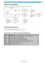
Страница 52: ...eral requirements 1 Serial port setup is 19200 8 N 1 2 Unless otherwise stated byte order is low byte first List of terms used for external interfaces Term Description LM Local Monitor serial communication port on the container unit LogMan Hand held datalog retriever terminals LogView PC software viewer for container datalog files SCCU Reefer Container Controller Unit Star Control RefCon Powerline...

Страница 53: ...edge alarms x x Initiate manual defrost x x Initiate Trip Start x x x Initiate Function and PTI test x x x Terminate Function and PTI test x x x Display Function and PTI test results x x x Retrieve datalog from unit x x x Save datalog file binary x x Save datalog file RefCon x Save datalog file CSV text x Display datalog file binary x x Display datalog file RefCon x Display datalog file CSV text x...

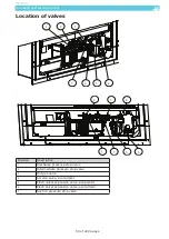
Страница 54: ... 1 5 7 6 4 Position Description 1 Discharge pressure stop valve 2 Intermediate pressure stop valve 3 Hot gas valve 4 Service valve economizer 5 Electronical expansion valve evaporator 6 Electronical expansion valve economizer 7 Suction pressure stop valve 1 7 6 5 4 3 2 ...

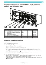
Страница 55: ...side Through inspection hatch 2 Relative humidity sensor RH 1 Inside Through inspection hatch 3 Evaporator temperature sensor Tevap 1 Inside Through inspection hatch 4 Supply temperature sensor Tsup 2 Outside 5 Return temperature sensor Tret 1 Inside Through inspection hatch 6 Economizer Suction Tempera ture optional Teco 1 Outside 7 Ambient temperature sensor Tamb 1 Outside 8 Air Exchange potenti...

Страница 56: ... the unit Check that the power fuses are not blown Check that 24VAC fuse F6 is not blown Check alarm list and clear alarms and alarm causes The unit is wired for emergency operation but the parameter F03 FC type under service menu is not set to NONE The menu F03 under service menu is set to NONE for emergency operation but the wires have not been correctly mounted for emergency operation 2 Unit st...

Страница 57: ...ngs If there is a problem with a sensor or a transmitter the X1 cable on the controller door must be disconnected to see if the defect is with the sensor transmitter or the controller door The proce dure is 1 Set unit to Manual Operation Mode by choosing Service Menu and Operation Mode and changing Auto to Manual 2 Disconnect the X1 cable from the controller door 3 After a while enter the Informat...

Страница 58: ...rning 118 Tcargo open Cargo Temperature Sensor Open Circuit Warning 119 Tcargo short Cargo Temperature Sensor Short Circuit Warning 120 Tcargo invalid Cargo Temperature Sensor Invalid Warning 121 Tevap open Evaporator Temperature Sensor Open Circuit Warning 122 Tevap short Evaporator Temperature Sensor Short Circuit Warning 123 Tevap invalid Evaporator Temperature Sensor Invalid Warning 124 Tsuc o...

Страница 59: ...loaded under supplied Alarm 428 U f ratio high Bad power supply voltage regulation out of order Alarm 429 U f ratio Bad power supply Fatal alarm 430 Cpr connection Power Cable From FC to Compressor Faulty Alarm 5 FC alarms 500 FC missing Frequency Communication Missing Fatal alarm 501 FC local control FC Local Mode Fault Alarm 508 FC short circ FC Short Circuit Fault Alarm Alarm 509 FC 24 V fault ...

Страница 60: ...s 800 Func test failed Function Test Fault Alarm 801 Controller Controller Internal Voltage Reference Fault Alarm 805 Idle current Unit Idle Overcurrent Fault Alarm 810 Mevap cur LO speed Evaporator Motor Low Speed Current Fault Alarm 811 Mevap cur HI speed Evaporator Motor High Speed Current Fault Alarm 812 Mevap current OFF Evaporator Motor Off Current Fault Alarm 813 Mevap direction Not impleme...

Страница 61: ...arning 958 Gnd ref HI Controller Internal Voltage Reference Fault Warning 959 RH sens sup LO Controller Internal Voltage Reference Fault Warning 960 RH sens sup HI Controller Internal Voltage Reference Fault Warning 961 Pdis sens sup LO Controller Internal Voltage Reference Fault Warning 962 Pdis sens sup HI Controller Internal Voltage Reference Fault Warning 963 Psuc sens sup LO Controller Intern...

Страница 62: ...ure in Tables starting starting p 204 the temperature sensor and cable are ok 3 Measure the voltage over the connector for Tret It should be between 4 80 and 5 05V DC a If the voltage is inside the above range connect sensor again Measure the voltage over the sensor and check voltage temperature according to Tables starting starting p 204 b If the voltage is outside the above range the controller ...

Страница 63: ...ng p 204 the temperature sensor and cable are ok 3 Measure the voltage over the connector for Tret it should be between 4 80 and 5 05V DC a If the voltage is inside the above range connect sensor again Measure the voltage over the sensor and check voltage temperature according to Tables starting p 204 b If the voltage is outside the above range the controller PCB is defect or other sensors may be ...

Страница 64: ...active see trouble shooting for AL 901 4 Measure the resistance between the two wires a If the resistance is out of range of the resistance and temperature table in Tables starting p 204 the temperature sensor and cable are defect and should be replaced b If the resistance is within range perform controller door check Trouble shooting for Star Cool Controller p 56 before replacing controller door ...

Страница 65: ...in Tables starting p 204 the temperature sensor and cable are ok 3 Measure the voltage over the connector for Tsup1 it should be between 4 80 and 5 05V DC a If the voltage is inside the above range connect sensor again Measure the voltage over the sensor and check voltage temperature according to Tables starting p 204 b If the voltage is outside the above range the controller PCB is defect or othe...

Страница 66: ...starting p 204 the temperature sensor and cable are ok 3 Measure the voltage over the connector for Tsup1 it should be between 4 80 and 5 05V DC a If the voltage is inside the above range connect sensor again Measure the voltage over the sensor and check voltage temperature according to Tables starting p 204 b If the voltage is outside the above range the controller PCB is defect or other sensors ...

Страница 67: ...e for sensor Tsup1 from the connector on the interface terminal block PCB according to the wiring schematics inside in the control cabinet 5 Measure the resistance between the two wires a If the resistance is out of range of the resistance and temperature table Tables starting p 204 the temperature sensor and cable are defect and should be replaced b If the resistance is within range perform contr...

Страница 68: ...re in Tables starting p 204 the temperature sensor and cable are ok 3 Measure the voltage over the connector for Tsup2 It should be between 4 80 and 5 05V DC a If the voltage is inside the above range connect sensor again Measure the voltage over the sensor and check voltage temperature according to Tables starting p 204 b If the voltage is outside the above range the controller PCB is defect or o...

Страница 69: ... starting p 204 the temperature sensor and cable are ok 3 Measure the voltage over the connector for Tsup2 It should be between 4 80 and 5 05V DC a If the voltage is inside the above range connect sensor again Measure the voltage over the sensor and check voltage temperature according to Tables starting p 204 b If the voltage is outside the above range the controller PCB is defect or other sensors...

Страница 70: ...ensor Tsup2 from the connector on the interface terminal block PCB according to the wiring schematics inside in the control cabinet 5 Measure the resistance between the two wires a If the resistance is out of range of the resistance and temperature table Tables starting p 204 the temperature sensor and cable are defect and should be replaced b If the resistance is within range perform controller d...

Страница 71: ...and temperature in Tables starting p 204 the temperature sensor and cable are ok 3 Measure the voltage over the connector for Tusda1 It should be between 4 80 and 5 05V DC a If the voltage is inside the above range connect sensor again Measure the voltage over the sensor and check voltage temperature according to table Tables starting p 204 b If the voltage is outside the above range the controlle...

Страница 72: ...see Tables starting p 204 the temperature sensor and cable are ok 3 Measure the voltage over the connector for Tusda1 It should be between 4 80 and 5 05V DC a If the voltage is inside the above range connect sensor again Measure the voltage over the sensor and check voltage temperature according to table in Tables starting p 204 b If the voltage is outside the above range the controller PCB is def...

Страница 73: ...active see trouble shooting for AL 901 4 Disconnect the sensor cable for sensor Tusda1 from the connector on the interface terminal block PCB according to the wiring schematics inside in the control cabinet 5 Measure the resistance between the two wires a If the resistance is out of range of the resistance and temperature table Tables starting p 204 the temperature sensor and cable are defect and ...

Страница 74: ...e Tables starting p 204 the temperature sensor and cable are ok 3 Measure the voltage over the connector for Tusda2 It should be between 4 80 and 5 05V DC a If the voltage is inside the above range connect sensor again Measure the voltage over the sensor and check voltage temperature according to table in Tables starting p 204 b If the voltage is outside the above range the controller PCB is defec...

Страница 75: ...ctive see trouble shooting for AL 901 4 Disconnect the sensor cable for sensor Tusda1 from the connector on the interface terminal block PCB according to the wiring schematics inside in the control cabinet 5 Measure the resistance between the two wires a If the resistance is out of range of the resistance and temperature table Tables starting p 204 the temperature sensor and cable are defect and s...

Страница 76: ...ture in table Tables starting p 204 the temperature sensor and cable are ok 3 Measure the voltage over the connector for Tusda3 It should be between 4 80 and 5 05V DC a If the voltage is inside the above range connect sensor again Measure the voltage over the sensor and check voltage temperature according to table in Tables starting p 204 b If the voltage is outside the above range the controller ...

Страница 77: ...ble Tables starting p 204 the temperature sensor and cable are ok 3 Measure the voltage over the connector for Tusda3 It should be between 4 80 and 5 05V DC a If the voltage is inside the above range connect sensor again Measure the voltage over the sensor and check voltage temperature according to table in Tables starting p 204 b If the voltage is outside the above range the controller PCB is def...

Страница 78: ...ctive see trouble shooting for AL 901 4 Disconnect the sensor cable for sensor Tusda1 from the connector on the interface terminal block PCB according to the wiring schematics inside in the control cabinet 5 Measure the resistance between the two wires a If the resistance is out of range of the resistance and temperature table Tables starting p 204 the temperature sensor and cable are defect and s...

Страница 79: ...resistance and temperature in table Tables starting p 204 the temperature sensor and cable are ok 3 Measure the voltage over the connector for Tcargo It should be between 4 80 and 5 05V DC a If the voltage is inside the above range connect sensor again Measure the voltage over the sensor and check voltage temperature according to table in Tables starting p 204 b If the voltage is outside the above...

Страница 80: ... and temperature in table Tables starting p 204 the temperature sensor and cable are ok 3 Measure the voltage over the connector for Tcargo It should be between 4 80 and 5 05V DC a If the voltage is inside the above range connect sensor again Measure the voltage over the sensor and check voltage temperature according to table in Tables starting p 204 b If the voltage is outside the above range the...

Страница 81: ...tive see trouble shooting for AL 901 4 Disconnect the sensor cable for sensor Tusda1 from the connector on the interface terminal block PCB according to the wiring schematics inside in the control cabinet 5 Measure the resistance between the two wires a If the resistance is out of range of the resistance and temperature table Tables starting p 204 the temperature sensor and cable are defect and sh...

Страница 82: ... and temperature in table Tables starting p 204 the temperature sensor and cable are ok 3 Measure the voltage over the connector for Tevap It should be between 4 80 and 5 05V DC a If the voltage is inside the above range connect sensor again Measure the voltage over the sensor and check voltage temperature according to table in Tables starting p 204 b If the voltage is outside the above range the ...

Страница 83: ...ture in table in Tables starting p 204 the temperature sensor and cable are ok 3 Measure the voltage over the connector for Tevap It should be between 4 80 and 5 05V DC a If the voltage is inside the above range connect sensor again Measure the voltage over the sensor and check voltage temperature according to table in Tables starting p 204 b If the voltage is outside the above range the controlle...

Страница 84: ...ntrol cabinet 3 If AL 901 is active see trouble shooting for AL 901 4 Measure the resistance between the two wires a If the resistance is out of range of the resistance and temperature table Tables starting p 204 the temperature sensor and cable are defect and should be replaced b If the resistance is within range perform controller door check Trouble shooting for Star Cool Controller p 56 before ...

Страница 85: ...e in table Tables starting p 204 the temperature sensor and cable are ok 3 Measure the voltage over the connector for Tsuc It should be between 4 80 and 5 05V DC a If the voltage is inside the above range connect sensor again Measure the voltage over the sensor and check voltage temperature according to table in Tables starting p 204 b If the voltage is outside the above range the controller PCB i...

Страница 86: ...rting p 204 the temperature sensor and cable are ok 3 Measure the voltage over the connector for Tsuc It should be between 4 80 and 5 05V DC a If the voltage is inside the above range connect sensor again Measure the voltage over the sensor and check voltage temperature according to table in section Tables starting p 204 b If the voltage is outside the above range the controller PCB is defect or o...

Страница 87: ...in the control cabinet 3 If AL 901 is active see trouble shooting for AL 901 4 Measure the resistance between the two wires a If the resistance is out of range of the resistance and temperature table Tables starting p 204 the temperature sensor and cable are defect and should be replaced b If the resistance is within range perform controller door check see Trouble shooting for Star Cool Controller...

Страница 88: ... table Tables starting p 204 the temperature sensor and cable are ok 3 Measure the voltage over the connector for Tamb It should be between 4 80 and 5 05V DC a If the voltage is inside the above range connect sensor again Measure the voltage over the sensor and check voltage temperature according to table in Tables starting p 204 b If the voltage is outside the above range the controller PCB is de...

Страница 89: ...s starting p 204 the temperature sensor and cable are ok 3 Measure the voltage over the connector for Tamb It should be between 4 80 and 5 05V DC a If the voltage is inside the above range connect sensor again Measure the voltage over the sensor and check voltage temperature according to table in Tables starting p 204 b If the voltage is outside the above range the controller PCB is defect or othe...

Страница 90: ...f AL 901 is active see trouble shooting for AL 901 4 Measure the resistance between the two wires a If the resistance is out of range of the resistance and temperature table Table starting p 204 the temperature sensor and cable are defect and should be replaced b If the resistance is within range perform controller door check Trouble shooting for Star Cool Controller p 56 before replacing controll...

Страница 91: ... and on the sensor Disconnect signal wire on interface terminal block PCB Measure voltage between wire and GND on interface terminal block PCB AKS If voltage is below 0 5V DC sensor or connection between sensor and cable is defect If voltage is between 0 5V DC and 4 5V DC continue to 4 NSK If voltage is below 0 37V DC sensor or connection between sensor and cable is defect If voltage is between 0 ...

Страница 92: ...d on the sensor Disconnect signal wire on interface terminal block PCB Measure voltage between wire and GND on interface terminal block PCB AKS If voltage is below 0 5V DC sensor or connection between sensor and cable is defect If voltage is between 0 5V DC and 4 5V DC continue to 4 NSK If voltage is below 0 37V DC sensor or connection between sensor and cable is defect If voltage is between 0 37V...

Страница 93: ...l wire on interface terminal block PCB Measure voltage between wire and GND on interface terminal block PCB AKS If voltage is below 0 5V DC sensor or connection between sensor and cable is defect If voltage is between 0 5V DC and 4 5V DC continue to 4 NSK If voltage is below 0 37V DC sensor or connection between sensor and cable is defect If voltage is between 0 37V DC and 4 0V DC continue to 4 4 ...

Страница 94: ...e sensor Disconnect signal wire on interface terminal block PCB Measure voltage between wire and GND on interface terminal block PCB AKS If voltage is below 0 5V DC sensor or connection between sensor and cable is defect If voltage is between 0 5V DC and 4 5V DC continue to 4 NSK If voltage is below 0 37V DC sensor or connection between sensor and cable is defect If voltage is between 0 37V DC and...

Страница 95: ...connect signal wire on interface terminal block PCB Measure voltage between wire and GND on interface terminal block PCB AKS If voltage is below 0 5V DC sensor or connection between sensor and cable is defect If voltage is between 0 5V DC and 4 5V DC continue to 4 NSK If voltage is below 0 37V DC sensor or connection between sensor and cable is defect If voltage is between 0 37V DC and 4 0V DC con...

Страница 96: ...onnect signal wire on interface terminal block PCB Measure voltage between wire and GND on interface terminal block PCB AKS If voltage is below 0 5V DC sensor or connection between sensor and cable is defect If voltage is between 0 5V DC and 4 5V DC continue to 4 NSK If voltage is below 0 37V DC sensor or connection between sensor and cable is defect If voltage is between 0 37V DC and 4 0V DC cont...

Страница 97: ...ansmitters in the configuration on menu F07 and F08 Criteria The saved Frecuency Converter ID does not match the new Frecuency Converter ID in the controller Controller action Replacement by new value from AAS system Log X Alarm X Alarm light On Consequence The unit will continue operation with AAS value Elimination The operator has to manually select the type of pressure transmitters in the confi...

Страница 98: ...ess than 230 Ω the cable is defect and must be replaced 3 Mount the cable for RH in controller cabinet and on the sensor Disconnect signal wire on interface terminal block PCB Measure voltage between wire and GND on the interface terminal block PCB If voltage is below 0 5V DC sensor or connection between sensor and cable is defect If voltage is between 0 5V DC and 10V DC continue to 4 4 Mount sign...

Страница 99: ...ck If the resistance is less than 230 Ω the cable is defect and must be replaced 3 Mount the cable for RH in controller cabinet and on the sensor Disconnect signal wire on interface terminal block PCB Measure voltage between wire and GND on the interface terminal block PCB If voltage is below 0 5V DC sensor or connection between sensor and cable is defect If voltage is between 0 5V DC and 10V DC c...

Страница 100: ... be replaced 3 Mount the cable for RH in controller cabinet and on the sensor Disconnect signal wire on interface terminal block PCB Measure voltage between wire and GND on the interface terminal block PCB If voltage is below 0 5V DC sensor or connection between sensor and cable is defect If voltage is between 0 5V DC and 10V DC continue to 4 4 Mount signal wire Measure voltage between SIGNAL and ...

Страница 101: ... cable for AirEx in controller cabinet and on the sensor Disconnect signal wire on interface terminal block PCB Measure voltage between wire and GND on the interface terminal block PCB If the voltage is over 4 0 V DC sensor or connection between sensor and cable is defect If the voltage is between 0 2 V DC and 4 0 V DC continue to 4 4 Mount signal wire Measure voltage between SIGNAL and GND If the...

Страница 102: ...the cable for AirEx in controller cabinet and on the sensor Disconnect signal wire on interface terminal block PCB Measure voltage between wire and GND on the interface terminal block PCB If the voltage is below 0 2V DC sensor or connection between sensor and cable is defect If the voltage is between 0 2V DC and 4 0V DC continue to 4 4 Mount signal wire Measure voltage between SIGNAL and GND If th...

Страница 103: ...cable for AirEx in controller cabinet and on the sensor Disconnect signal wire on interface terminal block PCB Measure voltage between wire and GND on the interface terminal block PCB If the voltage is below 0 2V DC sensor or connection between sensor and cable is defect If the voltage is between 0 0V DC and 4 0V DC continue to 4 4 Mount signal wire Measure voltage between SIGNAL and GND If the vo...

Страница 104: ...d for airflow 5 If condenser is blocked clean the condenser to secure cludding and dirt are removed 6 If alarm AL 500 FC missing is also active the fuse F6 inside in the control cabinet is most likely blown Replace the fuse Disconnect the cable for high pressure switch from the connector PCB according to the wiring schematics inside the control cabinet 7 Measure the voltage between the two connect...

Страница 105: ... the interface terminal block PCB above X33 and X34 They must be 220 kΩ 6 Turn unit on again Measure the voltage over the connector for Mevap1OH It should be between 4 80V DC and 5 05V DC a If the voltage is inside the above range connect sensor again Measure the voltage over the sensor and check the voltage If the voltage is less than 2 5V DC the measurement is ok If the alarm after 30 sec is sti...

Страница 106: ...the interface terminal block PCB above X33 and X34 They must be 220 kΩ 6 Turn unit on again Measure the voltage over the connector for Mevap2OH It should be between 4 80V DC and 5 05V DC a If the voltage is inside the above range connect sensor again Measure the voltage over the sensor and check the voltage If the voltage is less than 2 5V DC the measurement is ok If the alarm after 30 sec is stil...

Страница 107: ...k PCB above X33 and X34 They must be 220 kΩ 6 Turn unit on again Measure the voltage over the connector for McondOH It should be between 4 80V DC and 5 05V DC a If the voltage is inside the above range connect sensor again Measure the voltage over the sensor and check the voltage If the voltage is less than 2 5V DC the measurement is ok If the alarm after 30 sec is still active on the display the ...

Страница 108: ...rgo is unloaded run a PTI test and see if one of the motors or heater is using too much power 4 Check power cables for short circuits and damages 5 Check cables for heaters and motors for short circuits and damages Criteria Maximum current consumption has been exceeded Controller action Controller breaks supply Log X Alarm Alarm light Off Consequence Unit stops Elimination Log data Parm 1 Parm 2 P...

Страница 109: ...imit 525 Volt Controller action Controller breaks supply after 60 sec After 30 sec the unit restarts with a normal startup procedure Log X Alarm X Alarm light Quick flash Consequence Unit stops Elimination Alarm will be marked as inactive if another phase voltage measuring is below limit It may then be deleted Log data Parm 1 Parm 2 Parm 3 Parm 4 Parm 5 Active Inactive Low limit High limit Voltage...

Страница 110: ...ified level Defect Power Meas PCB Accompanied alarms N A Trouble shooting 1 Measure the voltage applied to the unit 2 Apply correct voltage to the unit The FC will not be able to maintain stable speed of the compressor motor due to a too low voltage and therefore the unit will make a restart 3 Measure the actual voltage and compare with the value in the display If the measurement differs the power...

Страница 111: ...It may then be deleted Log data Parm 1 Parm 2 Parm 3 Parm 4 Parm 5 Active Inactive Low limit High limit Voltage A D Channel 419 U1 3 under voltage Warning Description U1 3 under voltage Cause Indication of error in container supply voltage between phases 1 and 3 Trouble shooting See trouble shooting for AL 417 Criteria Value below low alarm limit 335 Volt Controller action Controller breaks supply...

Страница 112: ... by pressing selecting configuration then phase direction and then cw If condenser fan rotates in the wrong direction choose ccw This action is to be performed at every unit start up Criteria Value above upper alarm limit 20 Amp Controller action None Log X Alarm Alarm light Off Consequence Unit stops Elimination Log data Parm 1 Parm 2 Parm 3 Parm 4 Parm 5 Active Inactive High limit Present A D Ch...

Страница 113: ... frequency is out of specified range Loose flat cable between power meas PCB and terminal PCB Defect Power Meas PCB Accompanied alarms AL 424 may also be active Trouble shooting 1 Check or and replace flat power cable between power meas PCB and terminal PCB 2 Check if voltage on all 3 phases is within specified range 3 Verify that all 3 phases are applied to the unit 4 Verify that power frequency ...

Страница 114: ...ion Power frequency within range again Log data Parm 1 Parm 2 Parm 3 Parm 4 Parm 5 Active Inactive Frequency 426 Frequency too high Alarm Description Power Frequency Too High Alarm Cause Power generator adjusted to too high frequency Trouble shooting Possible causes The power frequency is out of specified range Accompanied alarms AL 423 or AL 425 may also be active Trouble shooting 1 Adjust the fr...

Страница 115: ...marked as inactive in alarm list when proper supply is established Alarm may then be deleted Log data Parm 1 Parm 2 Parm 3 Parm 4 Parm 5 U1 2 U2 3 U1 3 NetFreq n a 428 Voltage freq U f ratio high Alarm Description Bad power supply voltage regulation out of order Cause Power generator adjusted to too high voltage Trouble shooting Possible causes Failure in generator voltage control Accompanied alar...

Страница 116: ... Cpr connection Alarm Description Power Cable From FC to Compressor is Faulty Cause Indication of error with power cable between FC and compressor The compressor is not using any power Trouble shooting Possible causes The power cable between the FC and the compressor motor is defect The current measuring circuit in the FC is faulty The compressor motor is damaged Accompanied alarms N A Trouble sho...

Страница 117: ...ikely blown Replace the fuse 2 Verify that cable FC com is mounted correctly according to wiring diagram inside the controller cabinet and not being damaged 3 Check that power to the FC is not wired for emergency operation 4 Verify that there are correct voltages on all 3 phases for the FC 5 Measure with a multimeter that there is a small DC signal on the connector PCB for cable FC com a If there ...

Страница 118: ...n alarm list when local mode is reset on frequency converter Alarm may then be deleted Log data Parm 1 Parm 2 Parm 3 Parm 4 Parm 5 Active Inactive 508 FC short circ Alarm Description FC Short Circuit Alarm Cause Indication of defective cable compressor motor or FC Trouble shooting A16 Possible causes Short circuit on the FC power output Damaged cable and or plugs Accompanied alarms One or more AL ...

Страница 119: ...eq FC I FC Psuc Pdis 510 FC earth fault Alarm Description FC Earth Fault Alarm Cause Indication of problems with cable compressor or FC Trouble shooting A14 Possible causes Isolation damaged on the FC power output to the compressor Defect FC Damaged cable and or plugs Accompanied alarms One or more AL 5XX may also be active Trouble shooting 1 The power cable for the compressor motor Mcpr may have ...

Страница 120: ... may be defective and must be replaced if the alarm comes again If there is no FC replacement available the unit can be rewired for emergency operation See Emergency Operations p 50 6 Clean condenser Criteria FC overloaded Current above 38 Amp for approx 1 sec Controller action FC shut down Log X Alarm X Alarm light Slow flash Consequence Unit stop Elimination Alarm will be marked as inactive in a...

Страница 121: ...nd the compressor is not good enough Check the motor cable and replace it if it is defect Fasten bolts properly for better cooling 3 The compressor is wearing down and drawing increasingly power from the FC Check other alarms if there have been more alarms from the FC a If the ambient temperature is not high the compressor must be replaced b If the ambient temperature is high the compressor and FC...

Страница 122: ...arm may then be deleted Log data Parm 1 Parm 2 Parm 3 Parm 4 Parm 5 Active Inactive Freq FC I FC Psuc Pdis 515 FC over volt Alarm Description FC Overvoltage Fault Alarm Cause Indication of problems with supply voltage Trouble shooting A7 Possible causes The FC is supplied with too high voltage for continuous operation Defect FC Accompanied alarms AL 414 AL 415 AL 416 or AL 521 may be active Troubl...

Страница 123: ... generator is unstable adjust supply frequency to 50 55 Hz see Info Menu Viewing p 36 I22 to avoid self oscillation 5 If 1 to 4 do not solve the problem then replace the FC If no FC replacement is available the unit can be rewired for emergency operation Remind to use oscilloscope for determination of unstable supply from generator caused by uneven torque on generator cylinders Criteria FC cannot ...

Страница 124: ...ressor 3 Motor cable between FC and compressor may be jammed between FC and compressor Cooling of FC is unsufficient If this alarm appears more than once Dismount FC and check motor cable before mounting the FC again Fasten bolts properly for better cooling If no FC replacement is available the unit can be rewired for emergency operation See Emergency Operation p 50 Criteria FC temperature exceeds...

Страница 125: ... power for the unit is stable and within specification 3 Check the FC com cable for damages and loose connection 4 Check supply power cables for the FC 5 The FC may be defective and should be replaced If no FC replacement is available the unit can be rewired for emergency operation See Emergency Operation Criteria May occur if FC is activated too many times during a one minute period the primary s...

Страница 126: ... off for 10 min and then start it again If this alarm becomes active again the FC has an internal fault and must be replaced If no FC replacement is available the unit can be rewired for emergency operation See Emergency Operation p 50 Criteria Supply voltage of FC has exceeded 535 V AC 760 V DC Controller action None Log X Alarm X Alarm light Off Consequence If not solved this problem can cause F...

Страница 127: ...possible to insert an air gap gauge between FC and compressor 3 Motor cable between FC and compressor may be jammed between FC and compressor Cooling of FC is unsufficient If this alarm comes more than once Dismount FC and check motor cable before mounting the FC again Fasten bolts properly for better cooling If no FC replacement is available the unit can be rewired for emergency operation See Eme...

Страница 128: ...y that voltage levels are the same for all 3 phases diffence in voltage below 14V AC 3 Supply unit with correct power voltage according to specification 4 Replace the FC If no FC replacement is available the unit can be rewired for emergency operation Criteria More than 70 V diff in min max for phases in power supply Controller action None Log X Alarm X Alarm light Off Consequence If not solved th...

Страница 129: ...ain verify that the compressor starts again and is running 4 If the compressor cannot run or runs very shortly before this alarm appears again the compressor is defective and must be replaced 5 If the compressor can run several min without alarm the FC may be defective and must be replaced if the alarm appears again If no FC replacement is available the unit can be rewired for emergency operation ...

Страница 130: ... FC and the compressor is not good enough Check the motor cable and replace it if it is defect Fasten bolts properly for better cooling 3 The compressor is wearing down and drawing increasingly power from the FC Check other alarms if there have been more alarms from the FC a If the ambient temperature is not high the compressor must be replaced b If the ambient temperature is high the compressor a...

Страница 131: ... list when reset by FC Alarm may then be deleted Log data Parm 1 Parm 2 Parm 3 Parm 4 Parm 5 Active Inactive Freq FC I FC Psuc Pdis 566 FC undefined alarm Warning Description FC Undefined Alarm Cause The FC has an undefined alarm warning Trouble shooting Possible causes Defect FC Defect power cable from FC to compressor motor Accompanied alarms There may be other AL 5XX alarms Trouble shooting 1 T...

Страница 132: ...be other FC alarms AL 5XX and act accordingly to these 2 Turn the unit off for 10 min and then start it again If this alarm becomes active again the FC may have an internal fault and must be replaced If no FC replacement is available the unit can be rewired for emergency operation See Emergency Operation p 50 Criteria The FC has stopped due to an error and must be reset Controller action FC is bei...

Страница 133: ...ing X1 cable is defect Controller PCB defective Accompanied alarms AL 100 to AL 108 Trouble shooting 1 Verify all other sensor alarms AL 100 to AL 3XX and try to remove these alarms 2 If this alarm remains active replace main controller Criteria No valid control sensor values Controller action Unit stops Log X Alarm X Alarm light Quick flash Consequence Unit stop Elimination When one of the contro...

Страница 134: ...hooting 1 Verify that water cooling pipes are applied and water is running when selecting water cooling 2 Verify that the water is not too hot and not able to be used for cooling the unit Criteria Compressor discharge temperature exceeds limit for water cooling 60 C 140 F in more than 1 hour Controller action Water cooling is deactivated Log X Alarm X Alarm light Off Consequence Elimination Alarm ...

Страница 135: ... and gaskets 3 Check if there is enough refrigerant in the unit Check if the evaporator is filled with ice or dirt blocking air circulation Check if evaporator motors can rotate Watch fingers turn unit off first 4 Check if the condenser is filled with dirt and blocking air circulation Check if condenser motor can rotate Watch fingers turn unit off first 5 Check hot gas valve for leaking Let the co...

Страница 136: ...th ice or dirt blocking air circulation Check if evaporator motors can rotate Watch fingers turn unit off first 4 Check if the condenser is filled with dirt and blocking air circulation Check if condenser motor can rotate Watch fingers turn unit off first 5 Check hot gas valve for leaking Let the compressor run in manual for some time Stop compressor and see if the suction pressure rises more than...

Страница 137: ...607 AirEx open freeze Fatal Alarm Description Air exchange valve open in conflict with settings Cause Indication of user having left air exchange open Trouble shooting Possible causes AirExchange valve open in freeze mode AirExchange open in 50 60 RH Cable or airexchange sensor defect Accompanied alarms Possibly AL 305 Trouble shooting 1 See and clear error for alarm AL 305 2 Close air exchange If...

Страница 138: ... and test coil function 3 If it looks like the hot gas valve is working as usual run function test step compressor If alarms look for troubleshooting for these alarms 4 If no alarms run a manual activated defrost and follow the behavior of Tevap Tsuc Tret and Psuc 5 If Tevap or Tsuc behavior looks mysterious control function for Tevap follow troubleshooting for warning for Tevap AL 123 and Psuc AL...

Страница 139: ... Pdis 2 Start a manual defrost time to remove remaining ice now See if there has been used current for the heaters on the information menu Current phase 1 2 and 3 should be above 6 A when the heater symbol is shown on the display If current is lower check if there is power for the heaters 3 Run a PTI test after the cargo is unloaded Criteria Defrost time has exceeded 45 min Controller action None ...

Страница 140: ...t and may then be deleted Values must be valid for 120 sec to set alarm inactive Log data Parm 1 Parm 2 Parm 3 Parm 4 Parm 5 Active Inactive 612 FC trouble Alarm Description There have been several FC alarms within short time Cause The FC reports unstable operation within 30 min or a permanent FC error within the last 15 min Trouble shooting Possible causes Repeated FC errors Accompanied alarms Al...

Страница 141: ...t Slow flash Consequence Evaporator fan motor There is no or limited air circulation in the container Condenser fan motor There is limited capacity in the condenser Elimination When the evaporator fan motors and the condenser fan motor have been without errors for more than 1 hour this alarm is marked inactive and can be deleted Log data Parm 1 Parm 2 Parm 3 Parm 4 Parm 5 Active Inactive 614 Humid...

Страница 142: ...emergency mode Compressor defect Accompanied alarms There may be other alarms ex AL 306 Trouble shooting 1 Check and clear AL 306 first high pressure alarm 2 The discharge pressure is too high at start up unit will restart after a delay 3 Check and clear AL 5XX FC alarms first 4 Check wiring for the compressor motor especially if unit is in emergency mode 5 If this alarm remains active after sever...

Страница 143: ... maximum USDA temperature Treatment setpoint must be cooler Maximum USDA temperature must be warmer Attention Will require a longer duration 2 Close container doors 3 Check and clear other alarms first 4 Check if there is enough refrigerant in the unit 5 Check if the condenser is filled with dirt and blocking air circulation 6 Check if evaporator motors can rotate Watch fingers turn unit off first...

Страница 144: ... no better power supply is available 2 There is a failure in the power wiring for the unit Check that there are 3 valid phases for the unit 3 There is a fault in the phase direction detection circuit Turn unit off and on again and see if the phase can be detected now If phases still can t be detected replace the power module PCB 4 The main controller is defect Replace controller door Criteria User...

Страница 145: ...e power supply or cables before applying power again Criteria Supply voltages U1 2 U2 3 U1 3 are OK Power consumption too high The average current of the 2 highest currents is more than the double of the lowest current of I1 I2 or I3 Not checked during defrost The evaporator motors must run Controller action FC will soon trip with error 516 and stop compressor Log X Alarm X Alarm light Off Consequ...

Страница 146: ...XX alarms for cause Criteria One or more of the individual test steps have failed Controller action FC will soon trip with error 516 and stop compressor Log X Alarm X Alarm light Slow flash Consequence Deteriorated control precision and capacity Elimination When currents are normal it is marked as inactive in alarm list and may then be deleted Value must be valid for 30 sec to set alarm inactive L...

Страница 147: ...ct and controller door must be replaced b Measure voltage for all sensors Should be between 4 80V DC and 5 20V DC for temperature and pressure sensors Humidity sensor must be between 12 00V DC and 34 00V DC If not ok the sensor or cable is defect Replace sensor c Measure outlet on transformer between T3 and T4 Correct range 15 30V AC 24 30V AC Measure between T5 and T6 Correct range 18 86V AC 30 0...

Страница 148: ...tion Evaporator motor low speed current fault Cause Indication of defective motor or defective supply cables to motor Trouble shooting Possible causes Evaporator motor jammed or defect Evaporator motor cables defect Bad connection in plug Evaporator motor cables wired wrong in controller cabinet Accompanied alarms N A Trouble shooting 1 Check the evaporator motor fans can rotate freely Turn off po...

Страница 149: ... 2 1 2 6 Amp Controller action None Log X Alarm X Alarm light Slow flash Consequence Test failed Elimination Alarm may then be deleted after test completed Log data Parm 1 Parm 2 Parm 3 Parm 4 Parm 5 Active Inactive INom I1 I2 I3 812 Mevap current OFF Alarm Description Evaporator Motor Off Current Fault Cause Indication of defective motor contactor or contactor driver circuitry Trouble shooting Po...

Страница 150: ...able wired wrongly in controller cabinet or motor Accompanied alarms N A Trouble shooting 1 Check the condenser motor fan can rotate freely Turn off power first Replace motor or make it turn freely again 2 Check motor cable for damages 3 Check that the condenser motor cable is mounted correctly Criteria Condenser fan motor has exceeded current limit at low speed 0 2 0 3 Amp Controller action None ...

Страница 151: ...er action None Log X Alarm X Alarm light Slow flash Consequence Test failed Elimination Alarm may then be deleted after test completed Log data Parm 1 Parm 2 Parm 3 Parm 4 Parm 5 Active Inactive INom I1 I2 I3 817 Mcond current OFF Alarm Description Condenser Motor Off Current Fault Cause Indication of defective motor contactor or defective contactor driver circuitry Trouble shooting Possible cause...

Страница 152: ... Alarm light Slow flash Consequence Test failed Elimination Alarm may then be deleted after test completed Log data Parm 1 Parm 2 Parm 3 Parm 4 Parm 5 Active Inactive INom I1 I2 I3 821 Hevap current OFF Alarm Description Evaporator Heater Off Current Fault Cause Indication of defective heater contactor or defective contactor driver circuitry Trouble shooting Possible causes Defect heater contactor...

Страница 153: ...es One or more valves have leaks defect Accompanied alarms See other AL 84X alarms for valve failures Trouble shooting 1 Check and clear other valve alarms AL 84X Criteria Temperature indicates cooling Controller action None Log X Alarm X Alarm light Slow flash Consequence Test failed Elimination Alarm may then be deleted after test completed Log data Parm 1 Parm 2 Parm 3 Parm 4 Parm 5 81 0X T0 T0...

Страница 154: ...lve pos 14 P I diagr Run FT again If the test now is a pass the expansion valve is defective and should be replaced 3 Check that the cable for the expansion valve is not defect Replace cable if it is damaged 4 Disconnect the cable for valve and measure that there is voltage on the output for the expansion valve when it should open a If there is no voltage the controller PCB is defect Replace the c...

Страница 155: ...4 If the valve is opening and closing close service valve pos 30 P I diagr intermediate line Run the FT again it the test now is a pass the economizer valve is defect and should be replaced 3 Check that the cable for the expansion valve is not defect Replace cable if it is damaged 4 Disconnect the cable for valve and measure that there is voltage on the output for the expansion valve when it shoul...

Страница 156: ...ure after the valve pos 32 in the P I diagram the hot gas valve has a leak and should be replaced Internal parts of the hot gas valve can be replaced separately 3 Check that the cable for the hot gas valve is not defect Replace cable if it is damaged 4 Disconnect the cable for valve and measure that there is voltage on the output for the hot gas valve when it should open a If there is no voltage t...

Страница 157: ...low flash Consequence Test failed Elimination Alarm may then be deleted after test completed Log data Parm 1 Parm 2 Parm 3 Parm 4 Parm 5 Active Inactive T0 T0 diff Pdis Pdis old 846 FC Check Alarm Description Internal fault in FC Cause Indication of internal failure in the FC Trouble shooting Possible causes Internal failure in the FC Accompanied alarms N A Trouble shooting 1 Check and clear other...

Страница 158: ...dication of insufficient performance Trouble shooting Possible causes Doors are open The heaters do not operate correctly The cooling capacity is too limited There may not be enough refrigerant in the unit Accompanied alarms N A Trouble shooting 1 Verify that the doors are closed 2 If start temperature was below 5 C the heaters may be defective Start the heaters in manual mode and see if the curre...

Страница 159: ...below 0 C the heaters may be defect Start the heaters in manual mode and see if the current consumption is higher than 5 A each phase 3 The unit may need refrigerant Check if the small red balls in the sight glass in the receiver water cooling unit are not at the bottom when the unit is turned off Refill with refrigerant Criteria Set point 0 C was not reached within the 3 hour time limit Controlle...

Страница 160: ...ect Start the heaters in manual mode and see if the current consumption is higher than 5 A per phase else the heaters or the power cables for the heaters may be defect 3 The hot gas valve is not working properly and the heaters may be defective Check trouble shooting for the hot gas valve in alarm AL 844 4 See if the evaporator is filled with ice through the inspection holes Be careful with the ev...

Страница 161: ...efill with refrigerant Criteria Setpoint 18 C was not reached within the 3 hour time limit Controller action None Log X Alarm X Alarm light Slow flash Consequence Test failed Elimination Alarm may then be deleted after test completed Log data Parm 1 Parm 2 Parm 3 Parm 4 Parm 5 Active Inactive Tset Tact Tevap Tret Controller Alarms AL 9XX 900 User stop Fatal Alarm Description User stop was executed...

Страница 162: ... 2 Parm 3 Parm 4 Parm 5 Active Inactive 1 0 0 7 Tref1 8 Tevap 9 Tsup1 10 Tret 11 Tcarco 12 Tusda1 13 Tusda2 14 Tusda3 15 Tref2 16 Tsup2 17 Tamb 18 Tsuc 19 Trccu 902 Battery malfunction Alarm Description Battery Malfunctioning Cause Indication of defective battery Trouble shooting Possible causes The battery used for logging is defect Accompanied alarms AL 801 will be activated during FT or PTI tes...

Страница 163: ...Power must be ON Error must be off Replace RMM if not ok 5 Check cable to controller door If AL 903 is still active replace controller door Criteria Powerline monitor communication not possible Controller action None Log X Alarm X Alarm light Slow flash Consequence Container may drop out of remote monitor system Elimination Check replace modem or connection Log data Parm 1 Parm 2 Parm 3 Parm 4 Par...

Страница 164: ...Parm 1 Parm 2 Parm 3 Parm 4 Parm 5 Active Inactive 907 Realtime error Alarm Description Real time Clock Unreliable Cause Real time clock battery defect Trouble shooting Possible causes Real time clock battery defective Accompanied alarms AL 801 will be activated during FT or PTI test Trouble shooting 1 Turn on the unit and let it run for a couple of hours 2 Real time clock battery defect Replace c...

Страница 165: ...ndication of defective display or defective display driver circuitry Trouble shooting Possible causes Defect cable from controller PCB to display Defect display Defect controller PCB Accompanied alarms AL 801 will be activated during FT or PTI test Trouble shooting The unit will continue temperature control but settings and operation are not visible on the display 1 Try to adjust contrast See Cont...

Страница 166: ... Inactive 911 Battery voltage LO Warning Description Low Battery Voltage Cause Indication of defective battery Trouble shooting Possible causes Battery too old defective or used Battery cables defective Accompanied alarms AL 801 will be activated during FT or PTI test Trouble shooting 1 Check that connectors cables for the battery are not damaged If so replace the battery Criteria Battery voltage ...

Страница 167: ...escription Controller Internal Voltage Reference Fault Cause Indication of controller internal voltage reference fault Trouble shooting Possible causes Defect power supply for controller PCB Defect sensor pulling power supply down Defect controller PCB Accompanied alarms There may be sensor alarms AL 801 will be activated during FT or PTI test Trouble shooting 1 Check if there are other active sen...

Страница 168: ...oting 1 Check if there are other active sensor alarms Clear these alarms first using their trouble shooting 2 Check voltage level of 24V DC and 5V signals to see if power supply has an open circuit or other damages If voltages are ok the controller PCB is defect Replace controller door Criteria Reference ref below 2 75V DC Controller action None Log X Alarm Alarm light Off Consequence Elimination ...

Страница 169: ...sor alarms Clear these alarms first using their trouble shooting 2 Check voltage level of 24 V DC and 5 V signals to see if power supply has a short circuit or other damages If OK the controller PCB is defect Replace controller door Criteria Reference voltage 1 below 4 80 V DC Controller action None Log X Alarm Alarm light Off Consequence Temperature measurement to high Elimination Alarm will be m...

Страница 170: ...arms Clear these alarms first using their trouble shooting 2 Check voltage level of 24 V DC and 5 V signals to see if power supply has an open circuit or other damages If voltages are OK the controller PCB is defect Replace controller door Criteria Controller action None Log X Alarm Alarm light Off Consequence Temperature measurement to low Elimination Alarm will be marked as inactive in alarm lis...

Страница 171: ...I test Trouble shooting 1 Check if there are other active sensor alarms Clear these alarms first using their trouble shooting 2 Check voltage level of 24 V DC and 5 V signals to see if power supply has an open circuit or other damages If voltages are OK the controller PCB is defect Replace controller door Criteria Reference voltage 2 below 4 80V DC Controller action None Log X Alarm Alarm light Of...

Страница 172: ...rm 3 Parm 4 Parm 5 Active Inactive Low limit High limit Actual value A D channel 957 Gnd ref LO Warning Description Controller Internal Voltage Reference Fault Cause Indication of controller internal voltage reference fault Trouble shooting Possible causes Defect power supply for controller PCB Defect controller PCB Accompanied alarms There may be sensor alarms AL 801 will be activated during FT o...

Страница 173: ... 1 Check if there are other active sensor alarms Clear these alarms first using their trouble shooting 2 Check voltage level of 24 V DC and 5 V signals to see if power supply has an open circuit or other damages If voltages are OK the controller PCB is defect Replace controller door Criteria Ground reference voltage below 0 2V DC Controller action None Log X Alarm Alarm light Off Consequence Elimi...

Страница 174: ...e alarms first using their trouble shooting 2 Access the special menu by pressing for more than 3 sec Scroll down until you see the label U RH in the display The value of U RH should be in the range between 16 and 32 While displaying U RH disconnect RH from the terminals PCB and If U RH is now within the correct range the RH sensor is defect Replace the relative humidity sensor RH If U RH is still...

Страница 175: ... and humidity control will be affected and the unit may get damaged Supply unit with power according to specification If the voltage is ok the controller PCB is defect Replace controller door 3 Access the special menu by pressing for more than 3 sec Scroll down until you see the label U RH in the display The value of U RH should be in the range between 16 and 32 While displaying U RH disconnect RH...

Страница 176: ... display The value of U Pdis should be in the range between 4 80 V and 5 05 V DC 3 While displaying U Pdis remove the connector at Pdis If U Pdis is now inside the above range the Pdis pressure transmitter is defective Replace the Pdis pressure transmitter If U Pdis is still outside the above range proceed to next step 4 While displaying U Pdis disconnect Pdis from the terminals according to wirin...

Страница 177: ...wer supply for controller PCB Defect controller PCB Accompanied alarms There may be sensor alarms especially AL 203 AL 801 will be activated during FT or PTI test Trouble shooting 1 See Trouble shooting AL 961 Criteria Reference voltage Pdis above 5 20 V DC Controller action None Log X Alarm Alarm light Off Consequence Elimination Log data Parm 1 Parm 2 Parm 3 Parm 4 Parm 5 Active Inactive Low lim...

Страница 178: ...e in the range between 4 80 V and 5 05 V DC 3 While displaying U Psuc remove the connector at Psuc If U Psuc is now inside the correct above range 4 80 V 5 05 V DC the Psuc pressure transmitter is defective Replace the Psuc pressure transmitter If U Psuc is still outside the above range proceed to next step 4 While displaying U Psuc disconnect Pdis from the terminals according to wiring schematics...

Страница 179: ...e Low limit High limit Actual value A D channel 965 Controller sup LO Warning Description Controller Internal Voltage Reference Fault Cause Indication of controller internal voltage reference fault Trouble shooting Possible causes Defect power supply for controller PCB Defect controller PCB Accompanied alarms There may be sensor alarms especially AL 1XX and AL 2XX AL 801 will be activated during F...

Страница 180: ...ctivated during FT or PTI test Trouble shooting 1 Check if there are other active sensor alarms Clear these alarms first using their trouble shooting 2 Check voltage level of 24 V DC and 5 V signals to see if power supply has an open circuit or other damages If voltages are OK the controller PCB is defect Replace controller door Criteria Reference voltage above 5 20 V DC Controller action None Log...

Страница 181: ...While displaying U AirEx remove the connector at AirEx potentiometer If U AirEx is now inside the correct above range 4 80 5 05 V DC the AirEx potentiometer is defective Replace the AirEx potentiometer If U AirEx is still outside the above range proceed to next step 4 While displaying U AirEx disconnect AirEx from the terminals according to wiring schematics inside in the control cabinet If U AirE...

Страница 182: ...s first using their trouble shooting 2 Check voltage level of 24 V DC and 5 V signals to see if power supply has an open circuit or other damages If voltages are ok the controller PCB is defect Replace controller door Criteria Reference voltage AirEx above 5 20 V DC Controller action None Log X Alarm Alarm light Off Consequence Less accurate readings from measurement Elimination Alarm will be mark...

Страница 183: ... 80 and 5 05V DC 3 While displaying U Pspar remove the connector at Pspar If U Pspar is now inside the correct above range 4 80 5 05V DC the Pspar pressure sensor is defect Replace the sensor connected to Pspar If U Pspar is still outside the above range proceed to next step 4 While displaying U Pspar disconnect sensor from the terminals according to wiring schematics inside in the control cabinet...

Страница 184: ... 4 80 and 5 05V DC 3 While displaying U Pspar remove the connector at Pspar If U Pspar is now inside the correct above range 4 80 5 05V DC the Pspar pressure sensor is defect Replace the sensor connected to Pspar If U Pspar is still outside the above range proceed to next step 4 While displaying U Pspar disconnect sensor from the terminals according to wiring schematics inside in the control cabin...

Страница 185: ...nternal on the controller PCB and cannot be measured 981 Tinternal HI Warning Description Controller Internal Temperature Sensor High Temperature Fault Cause Indication of controller internal temperature sensor fault Trouble shooting Possible causes Defect power supply for controller PCB Defect controller PCB Accompanied alarms AL 801 will be activated during FT or PTI test Trouble shooting 1 Chec...

Страница 186: ...eria Controller action None Log X Alarm X Alarm light Off Consequence Elimination Replace software Log data Parm 1 Parm 2 Parm 3 Parm 4 Parm 5 Active Inactive 996 Software CRC error Alarm Description Prom CRC Fault Cause Trouble shooting Possible causes Validity check of the program failed Accompanied alarms AL 801 will be activated during FT or PTI test Trouble shooting 1 There is a fault on the ...

Страница 187: ...le shooting 1 There is a fault on the controller PCB Replace the controller door Criteria Controller action None Log X Alarm X Alarm light Consequence Elimination Log data Parm 1 Parm 2 Parm 3 Parm 4 Parm 5 Active Inactive 1 R 2 W Calibration of air exchange sensor Air exchange sensor calibration 1 Close the fresh air cover plate 2 In the Service menu line F06 Air exchange calibration select START...

Страница 188: ...perating and service manual Replacing of unit Handling of SCU unit during replacement is done by means of a special yoke see below sketch Depending on the model use either position 1 2 or 3 for the yoke Pos 1 Pos 3 Pos 2 ...

Страница 189: ...tly on the motor Do not disconnect the other cable connection which is connected directly in the motor cover Remove the 4 x M8 bolts that hold the evaporator motor bracket incl motor and fan Then the evaporator motor bracket with motor and fan can slide right through the inspection opening of the unit by dragging it towards yourself The evaporator bracket has to be tilted slightly downwards to pas...

Страница 190: ...l and disconnect the power supply to the motor by removing the motor cover and unscrew the earth wire which is placed directly on the motor Do not disconnect the other cable connection which is connected directly in the motor cover Replace the defective parts and reinstall the parts Prior to mounting the motor cover check the sealing for any damages if damaged the sealing must be replaced ...

Страница 191: ...rator fan module complete 3 Evaporator back plate 4 Fan grill 5 Side cover left and right 6 Evaporator The replacing of evaporator is done in the following steps 1 Evacuate refrigerant as described in this manual see p 197 2 Remove pos 5 3 Remove pos 1 4 Remove pos 4 5 Disconnect tray heater from pos 3 6 Disconnect cable for heating element on pos 6 7 Disconnect drain hose from evaporator backside...

Страница 192: ...down the unit see p 199 24 Charge unit as described in this manual see p 200 New model Position Description 1 Back plate unit 2 Evaporator The replacing of evaporator is done in the following steps 1 Evacuate refrigerant as described in this manual see p 197 2 Remove pos 1 3 Remove heating elements below pos 2 4 Remove the sensors for evaporator temperature suction temperature humidity 5 Dismount ...

Страница 193: ...Replacement of heating elements Dismount the back plate for the unit and replace the defect heating element After replacing heating elements reinstall back plate for unit Please note that the illustrated model may be different from the actual model ...

Страница 194: ...3 Remove the FC pos 2 and motor cable pos 3 4 Reinstall motor cable Please observe that the motor cable is not damaged and squeezed be tween compressor and FC Please observe correct tightening torque 5 Mount new FC Make sure that the FC is mounted correctly on the compressor and that there is no air gap between FC and compressor Please observe correct tightening torque 6 Reinstall cover for FC and...

Страница 195: ...essor foot is inserted into the bracket slot 9 Reinstall the compressor brackets Please observe correct tightening torque 10 Reinstall all pressure transmitters high pressure switch and temperature sensors Please observe correct tightening torque 11 Fasten all bolts for compressor stop valves Please observe correct tightening torque 12 Reinstall motor cable please observe that the motor cable is n...

Страница 196: ...urfaces 3 Check valve plate Exchange entire valve plate if damaged Determine the cause and eliminate it 4 Mount the cylinder head valve plate and new gaskets correctly If located in an inconvenient mounting position use mounting pins 5 Tighten the bolts in the illustrated sequence in two steps Starting with bolt no 1 and no 2 tightened firmly by hand and then in sequence no 3 to no 10 by tightning...

Страница 197: ... stopvalve pos 5 P I diagram approx 4 turns c Recovery equipment is set for vapor recovery d Open both service gauge manifold valves 5 Liquid recovery a Continue operation of unit b Close outlet valve pos 14 P I diagram from receiver and do a pump down of the low pressure side of the unit to approx 0 8 BarE c Turn off the unit d Set recovery equipment for liquid recovery e Open high pressure stopv...

Страница 198: ...vacuum is maintained then the compressor can be either changed see replacing of compressor or the unit can be started in normal operation If the vacuum pressure is not maintained there is a possible leak somewhere Check all hose connections between unit and vacuumpump If these are ok check the unit 11 Open compressor suction stopvalve compressor intermediate pressure stopvalve and com pressor disc...

Страница 199: ...ecommended to perform a pressure test Pressure test has the purpose of checking the piping system for leakages The pressuretest is done by means of a high pressurized gas ex N2 which is let into the piping system through the two evacuation points pos 6 27 P I diagram The procedure for this is as follows NOTE DO NOT USE OXYGEN O2 FOR A PRESSURE TEST 1 Install a service gauge manifold on the unit to...

Страница 200: ... of at least 6 hours to ensure a stable tendency During this observation time please observe the fol lowing 1 The red balls in the sight glass for the receiver are constantly at bottom level 2 Veco is more than 80 open for 0 5 hour 3 Vexp will steadily increase to 100 4 Psuc T0 is steadily going down If based on the above it is determined that the unit is too low on refrigerant charge additional r...

Страница 201: ...ge bubbling foam will occur This leakage detection test can also be done while the unit is running charged with refrigerant by means of a refrigerant detector or soap solution Leakage detection is also done during pump down of unit or compressor as described in this manual Fan motors In order to prevent a single wire from getting caught between Ground screw and junction box cover a cable tie colle...

Страница 202: ...gnets and reinstall the electrical coils on the two electronically expansionvalves pos 16 18 P I diagram 13 Open the stop valve pos 14 P I diagram 14 Power up the unit Compressor Check of oil level The oil level can be checked on the sight glass of the compressor During normal operation the oil level should be between 1 3 and 2 3 sight glass full Normal operation is when the unit has been running ...

Страница 203: ...l outlets are placed on a tee piece located on the compressor end opposite of the FC end Please observe that only one of the oil outlet ports is equipped with a schräder valve 2 Connect a service gauge manifold to the outlet port with schräder valve of the oil pump 3 Only connect the discharge hose to the outlet port of the oil pump Make sure that all stopvalves on the service gauge manifold are c...

Страница 204: ...IN 8511 or FB 3A according to AWS A 5 31 Example for product name Chem weld product 110 or Castolin 1802 N Atmosin 2 Use wet cloths to protect sensitive valves and other equipment against heat input during soldering and desoldering 3 Use inert back gas as Nitrogen N2 during soldering and desoldering Tables Datalog description Explanations of datalog loggings Temperatures are stored in C and are co...

Страница 205: ...ower voltage Highest power voltage of U1 U2 U3 V No Name Value Unit 6 I1 current Current I1 A 7 I2 current Current I2 A 8 I3 current Current I3 A 9 Ifc current Current FC A 10 Fcpr frequency Compressor frequency Hz 11 Heater status Heater on time 12 Reserved 13 Mevap status Evaporator motor OFF LO HI ERR 14 Mcond status Condenser motor OFF LO HI ERR No Name Value Unit 15 Tfc temperature Temperatur...

Страница 206: ... 16 Trip Start 1 Auto trip start 0 User trip start SW ver low SW ver high 0 user 1 MTS 2 CT SW revision 17 Sensor Calibrated 1 USDA 1 2 USDA 2 3 USDA 3 4 CARGO Old Cal Value New Cal Value n a n a 20 Power Up Unit run time hours Compr run time hours Mevap run time hours Mcond run time hours Hevap run time hours 21 User Wake up n a n a n a n a n a 22 Power Down SW ver 2 low est byte SW ver 2 high es...

Страница 207: ... Number of valid USDA sensors Duration min CT setpoint temp CT high temp limit Final setpoint temp 48 CT Failed 0 Sensor error 1 Aborted CT high temp limit USDA sensor 1 temp USDA sensor 2 temp USDA sensor 3 temp 50 Controller Internal Temperature T n a n a n a n a 90 Debug intern use 1 Alarm count Expected alarm count n a n a 91 FC status Communication rate n a Last alarm code 0 Clear 1 Time out ...

Страница 208: ...0 52 49 663 00 8 6 266 10 36 1 256 17 80 349 79 124 717 310 00 51 47 047 00 7 6 014 20 37 1 216 23 81 340 82 125 667 828 00 50 44 610 00 6 5 773 70 38 1 177 75 82 332 11 126 622 055 00 49 42 314 60 5 5 544 10 39 1 140 71 83 323 67 127 579 718 00 48 40 149 50 4 5 324 90 40 1 104 99 84 315 48 128 540 530 00 47 38 108 50 3 5 115 60 41 1 070 58 85 307 53 129 504 230 00 46 36 182 80 2 4 915 50 42 1 037...

Страница 209: ...97 1 256 17 176 349 79 255 717 310 00 60 47 047 00 19 6 014 20 99 1 216 23 178 340 82 257 667 828 00 58 44 610 00 21 5 773 70 100 1 177 75 180 332 11 259 622 055 00 56 42 314 60 23 5 544 10 102 1 140 71 181 323 67 261 579 718 00 54 40 149 50 25 5 324 90 104 1 104 99 183 315 48 262 540 530 00 53 38 108 50 27 5 115 60 106 1 070 58 185 307 53 264 504 230 00 51 36 182 80 28 4 915 50 108 1 037 40 187 2...

Страница 210: ...7 48 65 15 4 59 19 19 1 68 15 22 8 76 00 0 7 14 14 4 4 18 17 8 1 35 96 11 8 48 96 15 5 59 45 19 2 68 37 22 9 76 20 0 8 12 73 4 5 18 75 8 2 36 35 11 9 49 27 15 6 59 71 19 3 68 60 23 0 76 40 0 9 11 38 4 6 19 33 8 3 36 75 12 0 49 58 15 7 59 97 19 4 68 82 23 1 76 60 1 0 10 09 4 7 19 90 8 4 37 14 12 1 49 89 15 8 60 23 19 5 69 04 23 2 76 80 1 1 8 84 4 8 20 47 8 5 37 53 12 2 50 19 15 9 60 48 19 6 69 27 2...

Страница 211: ...96 73 171 14 120 13 224 81 139 01 278 47 155 07 332 14 169 16 11 60 9 09 65 27 65 75 118 93 97 43 172 59 120 69 226 26 139 48 279 92 155 48 333 59 169 52 13 05 11 52 66 72 66 79 120 38 98 15 174 05 121 24 227 71 139 95 281 37 155 88 335 04 169 88 14 50 13 84 68 17 67 82 121 83 98 85 175 50 121 80 229 16 140 41 282 82 156 27 336 49 170 24 15 95 16 09 69 62 68 85 123 28 99 55 176 95 122 34 230 61 14...

Страница 212: ... h 0 20 0 1 45 60 2 25 120 3 35 180 0 30 5 1 50 65 2 35 125 3 40 185 0 50 10 1 55 70 2 40 130 3 50 190 0 65 15 1 65 75 2 50 135 3 60 195 0 80 20 1 70 80 2 55 140 3 65 200 0 85 25 1 75 85 2 65 145 3 80 205 0 95 30 1 90 90 2 70 150 3 85 210 1 05 35 1 95 95 2 80 155 3 95 215 1 15 40 2 00 100 2 90 160 4 00 220 1 20 45 2 05 105 3 00 165 1 30 50 2 10 110 3 10 170 1 35 55 2 20 115 3 20 175 Relative Humid...

Страница 213: ...13 1 25 1 438 20 86 3 30 8 100 117 48 1 30 1 600 23 21 3 35 8 263 119 84 1 35 1 763 25 57 3 40 8 425 122 19 1 40 1 925 27 92 3 45 8 588 124 56 1 45 2 088 30 28 3 50 8 750 126 91 1 50 2 250 32 63 3 55 8 913 129 27 1 55 2 413 35 00 3 60 9 075 131 62 1 60 2 575 37 35 3 65 9 238 133 99 1 65 2 738 39 71 3 70 9 400 136 34 1 70 2 900 42 06 3 75 9 563 138 70 1 75 3 063 44 43 3 80 9 725 141 05 1 80 3 225 4...

Страница 214: ... 2 4 6 21 90 04 0 8 0 98 14 21 2 45 6 37 92 41 0 85 1 14 16 58 2 5 6 53 94 78 0 9 1 31 18 95 2 55 6 70 97 15 0 95 1 47 21 32 2 6 6 86 99 52 1 1 63 23 69 2 65 7 02 101 89 1 05 1 80 26 06 2 7 7 19 104 26 1 1 1 96 28 43 2 75 7 35 106 63 1 15 2 12 30 80 2 8 7 51 109 00 1 2 2 29 33 17 2 85 7 68 111 37 1 25 2 45 35 54 2 9 7 84 113 74 1 3 2 61 37 91 2 95 8 00 116 11 1 35 2 78 40 28 3 8 17 118 48 1 4 2 94...

Страница 215: ... 08 1 25 6 00 87 02 3 30 22 40 324 88 1 30 6 40 92 82 3 35 22 80 330 69 1 35 6 80 98 63 3 40 23 20 336 49 1 40 7 20 104 43 3 45 23 60 342 29 1 45 7 60 110 23 3 50 24 00 348 09 1 50 8 00 116 03 3 55 24 40 353 89 1 55 8 40 121 83 3 60 24 80 359 69 1 60 8 80 127 63 3 65 25 20 365 50 1 65 9 20 133 43 3 70 25 60 371 30 1 70 9 60 139 24 3 75 26 00 377 10 1 75 10 00 145 04 3 80 26 40 382 90 1 80 10 40 15...

Страница 216: ...0 290 16 1 5 00 72 54 2 55 20 50 297 414 1 05 5 50 79 794 2 6 21 00 304 668 1 1 6 00 87 048 2 65 21 50 311 922 1 15 6 50 94 302 2 7 22 00 319 176 1 2 7 00 101 556 2 75 22 50 326 43 1 25 7 50 108 81 2 8 23 00 333 684 1 3 8 00 116 064 2 85 23 50 340 938 1 35 8 50 123 318 2 9 24 00 348 192 1 4 9 00 130 572 2 95 24 50 355 446 1 45 9 50 137 826 3 25 00 362 7 1 5 10 00 145 08 3 05 25 50 369 954 1 55 10 ...

Страница 217: ...1 87 8 4 21 30 22 0 2 42 1 33 8 0 92 32 89 6 4 17 29 20 2 2 36 2 35 6 0 88 33 91 4 4 13 28 18 4 2 30 3 37 4 0 86 34 93 2 4 08 27 16 6 2 24 4 39 2 0 83 35 95 0 4 04 26 14 8 2 17 5 41 0 0 80 36 96 8 3 99 25 13 0 2 11 6 42 8 0 77 37 98 6 3 94 24 11 2 2 05 7 44 6 0 74 38 100 4 3 89 23 9 4 2 00 8 46 4 0 72 39 102 2 3 84 22 7 6 1 94 9 48 2 0 69 40 104 0 3 78 21 5 8 1 88 10 50 0 0 67 41 105 8 3 73 20 4 0...

Страница 218: ...x Lobular Socket Screw M6 9 Compressor Cylinder Head Hex Head M10 70 Bearing Cover Hex Socket Counters Head Bolt M10 54 Oil Pump Cover Hex Head Bolt M8 10 Sight Glass Hex Head 60 Terminal Block Hex Socket Counters Head Bolt M6 14 Pressure Transmitter AKS Hex Head 18 Pressure Transmitter NSK Hex Head 14 High Pressure Switch Hex Head 14 Receiver Water Inlet Coupling Female 70 Water Outlet Coupling M...

Страница 219: ... Point 29 Suction Pressure Transmitter P suc 30 36 35 34 20 20 33 RH M M 21 22 19 23 24 24 25 1 1 8 3 4 1 2 17 1 2 15 14 1 2 13 1 2 1 2 Water Inlet Water Outlet 3 4 7 1 2 16 9 M 8 32 1 2 1 2 1 2 10 35 37 10 3 4 26 27 P 28 FC 2 18 6 5 P PS 3 4 Motor 1 Low Pressure Stage High Pressure Stage 11b Air Release Valve old model 11a 11a 12 P 31 29 Note Please be advised that the sensors P eco and T eco can...

Страница 220: ...219 of 222 pages Operating and service manual Controller Unit Illustration ...

Страница 221: ...Operating and service manual 220 of 222 pages Star Cool Unit installation dimensions ...

Страница 222: ...221 of 222 pages Operating and service manual ...

Страница 223: ... x AWG 18 3 1 K3 Hevap 7 6 3 4 Vexp Vhg Veco FC pwr 4 RMM com 5 3 1 2 3 1 2 3 0VAC 42 92 X50 J5 GND 90 93 SIGNAL GND 43 94 44 SIGNAL GND SIGNAL 10 24 3 GND SIGNAL 40 5 4 Keypad Controller Hatch Inside Box 1 LCD Display Inside Box Inside Box 89 2 Outside Box 2 Outside Box LEDs 24VAC 10 0VAC 1 FC com 4 1 2 1 3 2 3 4 5 3 6 1 6 2 3 4 L1 L3 5 L2 6 2 X51 J3 4 1 2 4 4 7 5 2 4 3 1 6 3 6 2 1 2 3 4 6 3 RMM ...

Страница 224: ...ment is available 24 hours a day 7 days a week providing easy access to the answers you need For further troubleshooting help go to our website URL m starcool com or simply scan the QR code with Your smartphone Bjerndrupvej 47 6360 Tinglev Denmark Phone 45 73 64 34 00 Fax 45 73 64 35 69 E mail starcool starcool com www starcool com Copyright Maersk Container Industry AS Operating and service manua...

Отзывы: