Operating and service manual
108 of 222 pages
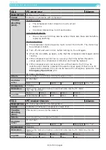
414
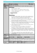
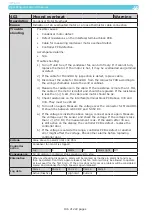
U1-2 over voltage
Fatal
Alarm
Description
U1-2 over voltage
Cause
Indication of error in container supply voltage between phases 1 and 2
Trouble
shooting
Possible causes:
•
The unit is supplied with a voltage above specified level.
Accompanied alarms:
•
N/A.
Trouble shooting:
1) Measure the voltage applied to the unit.
2) Apply correct voltage to the unit.
The FC will be destroyed if it is running at a too high voltage.
3) Measure the actual voltage and compare with the value in the display. If
the measurement differs the power module PCB may be defective. Replace
or bypass power module PCB by pressing
selecting configuration then
phase direction and then cw. If condenser fan rotates in the wrong direction,
choose ccw. This action is to be performed at every unit start up
Criteria
Value above top alarm limit 525 Volt
Controller
action
Controller breaks supply after 60 sec. After 30 sec. the unit restarts with a normal
startup procedure.
Log
X
Alarm
X
Alarm light
Quick flash
Consequence
Unit stops
Elimination
Alarm will be marked as inactive if another phase voltage measuring is below limit. It
may then be deleted.
Log data
Parm 1
Parm 2
Parm 3
Parm 4
Parm 5
Active/Inactive Low limit
High limit
Voltage
A/D Channel
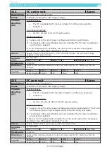
415
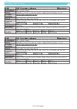
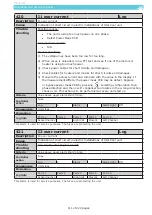
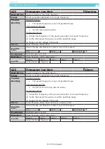
U2-3 over voltage
Fatal
Alarm
Description
U2-3 over voltage
Cause
Indication of error in container supply voltage between phases 2 and 3
Trouble
shooting
For trouble shooting see AL 414
Criteria
Value above top alarm limit 525 Volt
Controller
action
Controller breaks supply after 60 sec. After 30 sec. the unit restarts with a normal
startup procedure.
Log
X
Alarm
X
Alarm light
Quick flash
Consequence
Unit stops
Elimination
Alarm will be marked as inactive if another phase voltage measuring is below limit. It
may then be deleted.
Log data
Parm 1
Parm 2
Parm 3
Parm 4
Parm 5
Active/Inactive Low limit
High limit
Voltage
A/D Channel


