Standard Pump SP-800DD Скачать руководство пользователя страница 6

6

Standard Pump Operating Instructions and Parts Manual (OIPMS0611)

Assembly

1

.  Remove the pump and motor from packaging. 

2 .  Inspect all contents for damage .

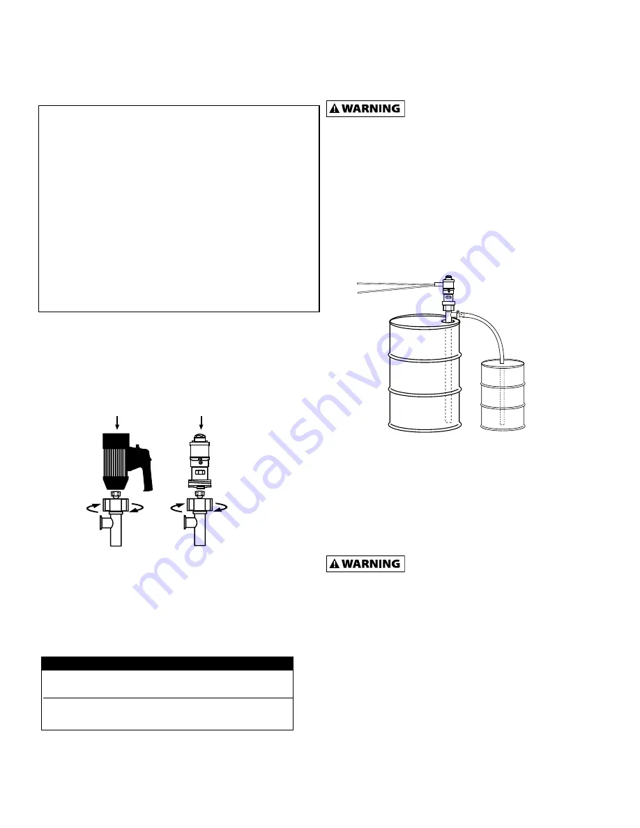
3.  Couple the motor to the pump tube by using the Hex Nut 

(see Figure 1) .

4.  First pump clean water in order to familiarize yourself with 

the pump’s operation, flow rate, discharge pressure and 

motor speed . 

5.  It is recommended to thoroughly clean and sanitize models 

SP-8800 & SP-8900 before operation.

Do not use these pumps for the transfer of 

flammable or combustible products or in an 

environment where flammable or combustible fumes are present 
unless used in conjunction with an Explosion Proof Motor or 
SP-A1FP / SP-A2 Series air motor. Please contact the factory or 
authorized distributor with any questions regarding this matter 
(see page 24).

General Operation Guide  (SP-8800 & SP-8900)

1

.  Use closed top drum or other cover to avoid possible 

contamination .

2.  Once the pump is fully cleaned, assembled and all 

connections are securely fastened, insert the pump into the 

drum or tank . 

3.  It is recommended to attach a suitable hose or pipe to the 

pump discharge.

4.  If you opt to use a hose, fasten the hose to the hose 

barb with a suitable hose clamp that exceeds the pump 
discharge pressure.

Make sure the hose meets the pump 
discharge pressure requirements (SP-8800 

= 16 psi (1,1 bar)) / (SP-8900 = 32 psi (2,2 bar). It is 
recommended to use a hose that is rated 4 x the pump 
discharge pressure. Ex: 32 x 4 = 128 psi (9 bar). 

5.  Turn the motor to the “ON” position. 
6.  After use, clean the pump and store vertically. 

Disassembly / Cleaning Procedures  

(SP-8800 & SP-8900)

1.  In order to clean a majority of the residue from the pump 

tube, immerse the pump into a 55 Gallon Drum of water 
or a non-flammable, food safe cleaning agent. Allow the 
pump to circulate the water for 3 minutes.  

2.  For a more thorough cleaning remove the motor from the 

pump tube by loosening the connection nut (P/N: 8842) 


(see Figure 2) . 

SP-8800 & SP-8900 SERIES

Note: 

Flow rates are based on water. As viscosity increases, the flow 

rate will decrease .


Specifications

Models SP-8800 & SP-8900

Maximum Liquid

Temperature  . . . . . . . . . . . . . . . . . . . .175º

 F (79

º C)

Pump Type  . . . . . . . . . . . . . . . . . . . . . . .Centrifugal
Pump Speed  . . . . . . . . . . . . . . . . . . . . .10,000 RPM

Max. Flow Rate 

SP-8800

  . . . . . . . . . . . . . . . . . . 32 GPM (121 LPM)


SP-8900

  . . . . . . . . . . . . . . . . . . . . 15 GPM (57 LPM)

Max. Discharge Pressure  SP-8800

  . . . . . . . . . . . . . . . . . . . . . . . . 16 psi (1,1 bar)


SP-8900

  . . . . . . . . . . . . . . . . . . . . . . . . 32 psi (2,2 bar)

Wetted Materials  . . . . . . . . . . . .SS 316, Buna & Teflon 

Immersion Length

  . . . . . . . . . . .47" (1200 mm) (Tanks)


39

" (1000 mm) (Drums & Barrels)

Discharge Port

  . . . . . . . . . . . . . . . . . . . .1 .0"

 (25mm) Hose Barb & 

 1 .5" (38 mm) Tri-Clamp
Motors  . . . . . . . . . . . . . . . . . . . . . . . . . . . . .SP-280P Series, SP-ENC Series,
 

SP-A1FP, SP-A2 Series

Electric

Air

Figure 1

Model 

Air Connection 

Consumption

 SP-A1FP


.125" (3,2 mm) 

28 CFM @ 90 psi 


13 .2 L/sec @ 6,2 bar


SP-A2L


.25" (6,3 mm) 

28 CFM @ 90 psi 


SP-A2


13 .2 L/sec @ 6,2 bar

Note: 

For optimum performance make sure proper size air  

lines are installed .

Air Line

Air Exhaust

Note: 

Recommend plumbing discharge air away from drum or 

tank to prevent possible contamination . Left port is air intake, 

right port is air exhaust.

Содержание SP-800DD

Страница 1: ...100 SP 8200 Series 2 SP 8800 SP 8900 Series 6 SP 800SR Series 10 SP 800DD Series 11 Ultra Mass 8500 Series 16 Ultra Mag 8300 Series 18 Flow Meter Pump Systems 8320 Series 20 Motors 22 Hazardous Duty E...

Страница 2: ...liarize yourself with the pump s operation flow rate discharge pressure and motor speed 9 Before starting the pump confirm the discharge hose is securely fastened to the receiving vessel in order to p...

Страница 3: ...00 16 psi 1 1 bar SP 8200 32 psi 2 2 bar It is recommended to use a hose that is rated 4 x the pump discharge pressure Ex 32 x 4 128 psi 9 bar 5 Turn the motor to the ON position 6 After use clean the...

Страница 4: ...9 Insert screwdriver through bearing unit P N 1038 see Figure 8 When replacing the drive shaft in the bearing unit P N 1038 during reassembly make sure the drive shaft is inserted through the spacer i...

Страница 5: ...TFE 39 1000 mm 47 1200 mm Connection Flange SS316 O Ring Buna Tri Clamp SS316 Hose Barb SS316 1 25 mm Inner Outer Tube Assembly SS316 39 1000 mm 47 1200 mm O Ring Buna 2 per set Pump Housing SS316 w P...

Страница 6: ...ar It is recommended to use a hose that is rated 4 x the pump discharge pressure Ex 32 x 4 128 psi 9 bar 5 Turn the motor to the ON position 6 After use clean the pump and store vertically Disassembly...

Страница 7: ...shafts remove the impeller P N 8827 or P N 8927 see Figure 3 5 Remove O ring P N 8830 from drive shaft P N 8806 or 8807 located behind impeller P N 8827 or P N 8927 see Figure 4 6 Remove the Pump Hou...

Страница 8: ...1 Remove guide sleeve P N 8811 from drive shaft P N 8806 or P N 8807 see Figure 9 12 Secure drive shaft P N 8806 or P N 8807 with grip locks Remove coupling P N 1004 bearings P N 1038 2 bearing spacer...

Страница 9: ...FE 39 1000 mm 47 1200 mm Inner Tube Assembly SS316 39 1000 mm 47 1200 mm O Ring Buna 2 Per Set O Ring Buna Tri Clamp SS316 Hose Barb SS316 1 00 25 mm Outer Tube Assembly SS316 39 1000 mm 47 1200 mm Pu...

Страница 10: ...ith a suitable hose clamp that exceeds the pump discharge pressure 4 Make sure the speed control knob on the motor is turned to the MIN position completely counterclockwise 5 Turn the motor switch to...

Страница 11: ...turns in a clockwise direction Use the pump arrow to verify proper direction If the pump rotates counterclockwise the internal components will disassemble Do not use these pumps for the transfer of f...

Страница 12: ...7 x 4 348 psi 24 3 bar Maintenance DISASSEMBLY CLEANING PROCEDURES SP 800SR SP 800DD 1 Remove motor from pump tube For models SP 800SR loosen Hex Nut in clockwise rotation see Figure 3 For models SP 8...

Страница 13: ...shaft onto bearing housing shaft see Figure 9 6 Thread rotor onto drive shaft see Figure 8 7 Thread stator can onto pump body see Figure 7 8 Apply a suitable lubricant on rotor 9 Once Bearing Housing...

Страница 14: ...Sizes SP 1851 39 801 Pump Sizes SP 751 39 SP 752 39 SP 1851 47 802 Pump Sizes SP 751 47 SP 752 47 803 12 Stator Buna SS316 Tube Size 751 816 Size 752 817 Size 1851 818 PTFE Stator Insert Only Size 75...

Страница 15: ...Sizes SP 751 39 SP 752 39 SP 1851 47 802 Pump Sizes SP 751 47 SP 752 47 803 11 Stator Buna SS316 Tube Size 751 816 Size 752 817 Size 1851 818 PTFE Stator Insert Only Size 751 822 Size 752 823 Size 185...

Страница 16: ...ry or death Operation Ultra Mass Series 1 Please refer to the Operation SP 800SR Series portion of these operating instructions on page 10 for the pump and motor portion of this system 2 For informati...

Страница 17: ...e 1851 710 Size 752 709 10 Gasket PTFE 731 11 Outer Tube Assembly SS316 Pump Size SP 1851 39 801 Pump Size SP 752 39 802 12 Stator PTFE Insert Only Size 1851 824 Size 752 823 13 Stator Tube SS316 Size...

Страница 18: ...ration Ultra Mag Series 1 Please refer to the Operation SP 800SR series portion of these operating instructions on page 10 for the pump and motor portion of this system 2 For information regarding the...

Страница 19: ...ize 1851 710 Size 752 709 10 Gasket PTFE 731 11 Outer Tube Assembly SS316 Pump Size SP 1851 39 801 Pump Size SP 752 39 802 12 Stator PTFE Insert Only Size 1851 824 Size 752 823 13 Stator Tube SS316 Si...

Страница 20: ...or death Operation 1 Please refer to the Operation SP 800SR Series portion of these operating instructions on page 10 for the pump and motor portion of this system 2 For information regarding the cal...

Страница 21: ...PTFE 735 8 Drive Shaft SS316 705 9 Rotor SS316 710 10 Gasket PTFE 731 11 Outer Tube Assembly SS316 801 12 Stator PTFE Insert Only 824 13 Stator Tube SS316 876 14 Stator Tube for Bagliners SS316 876BL...

Страница 22: ...t Armature 110 120V 220 240V Stator 110 120V 220 240V Guide disc Rod connector Pressure spring Brush holder Carbon brush 110 120V 220 240V Motor housing plastic Star washer Fan Overload switch 8 5 amp...

Страница 23: ...plug 110 120V 220 240V Hexagon nut Rod connector Brush holder Carbon brush 110 120V 220 240V Star washer Overload switch 8 5 amp 110 120V 5 amp 220 240V low voltage release EMI Filter Repair kit 110 1...

Страница 24: ...nd 10 A1 adapter 1 2 3 4 5 6 7 8 9 10 11 12 13 14 PART NUMBER SAF350 SAC229 SAC228A SAG549 SAC617 SAC527 SAE899 SAC616 SAC190A SAE893 SD324A SAE896 SK285 9007 DESCRIPTION ITEM NUMBER PART NUMBER DESCR...

Страница 25: ...ive Body gasket Body Key Rotor assembly Push pin Vane spring Vane End plate dead Bearing dead end End cap gasket End cap dead end Muffler assembly Felt 1 1 1 1 4 1 2 1 1 1 2 4 4 1 1 1 1 1 1 AC998 AK42...

Страница 26: ...g a cast iron or aluminum case or the steel shaft of the air motor Note that electric motor enclosures for both class I and II hazardous locations can be made of iron steel copper bronze or aluminum U...

Страница 27: ...the instructions given in this material Specific exceptions include Consumable items such as motor brushes bearings couplings and impellers Motor brushes typically have a life span of approximately 70...

Страница 28: ...h_______________________ Executive Director 3 A Sanitary Standards Inc The issuance of this authorization for the use of the 3 A Symbol is based upon the volun tary certification by the applicant for...

Отзывы: