


- 58 -
EN
1. CHARACTERISTICS OF THE DEVICE
The housing is made of stainless steel. The tabletop is mounted on a base with four feet, by means of which
you can level the grill. Leveling is possible within the range of ±10mm.
The main components of the device include: worktop with heated working plate (steel or chromed), gas
valve and main 6,5kW burner. The panel contains a gas valve, a spark generator, a safety thermostat, and a
waste drawer.
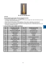
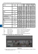
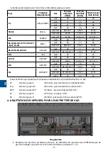
The device is equipped with a set of nozzles.
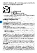
2. GRILL INSTALLATION
•
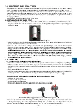
The grill with base should be placed on a stable surface in a closed room with the power off. Then level
the grill with the base by means of the feet in the body or in the base of the grill.
adjustable foot
•
Place the grill so that it is accessible at least from the front. There should be a wall made of non-combu-
stible materials behind the device.
•
The device can be set up in a row of appliances. If the appliance is not set up in a row with other devices
of the same line, the walls adjacent to the appliance (rear and side) should be made of non-combustible
materials.
•
The appliance is sold for a specific type of gas, as certified on the rating plate. Any change to the
type of gas can only be made by a qualified and authorized installers and must be included in the
warranty card attached to the appliance. The devices sealed and protected by the manufacturer
could only be handled by qualified installers after authorization and training provided by the Tech-
nical Service of STALGAST.
3. CONNECTION
3.1. Conditions for connection to mains:
•
You must check if voltage in grid is equal to the grid indicated on device’s rating plate.
•
To plug the device in electricity network you must perform plugging of the power cord in the terminal
box placed on the back wall of the device.
The power cord with a plug IS NOT the part of the set and
you must buy it.
•
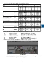
You must necessarily join the device to the installation of equalising electrical potentials with the help of
equipotential bolt placed in the back of the device. It is marked by the following symbol:
.
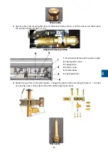
To join the device to the installation of equalising electrical potentials, you must:
•
Remove the nut from the bolt
•
Introduce equpotential’s cable
•
Tighten the nut until it stops
•
You must plug the second end of equipotential cable in the countervailing rail.
Connection of the device with installation of equalising electrical potentials.
The power cord should be flexible, oil-resistant, earthed, polychloroprene-coated (type H07RN-F 3G 1.5
mm
2
). It can be made by the manufacturer and available from him or in specialist repair shops.
Содержание 9730110
Страница 2: ... 2 1 3 4 6 5 2 1 2 3 ...
Страница 105: ......
Страница 106: ......
Страница 107: ......
Страница 108: ......