Page 36
TROUBLESHOOTING
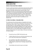
GENERAL TROUBLESHOOTING GUIDELINES
This section outlines several tests to systematically identify and isolate problems
with the electrical system and the drive train. This troubleshooting section is
organized into three basic problem sections: Electrical System, Console
Diagnostics, and the Drive Train. Perform the tests in exactly the same order as
written. Refer to the “Parts Removal and Replacement” section of this manual
for any disassembly and assembly instructions. To order a replacement part, or
to get help with the troubleshooting process, contact the Customer Service
Department of StairMaster Health and Fitness Products™ at (800) 331-3578.
International customers should contact their local distributor or call
(425) 823-1825.
SYSTEMATIC ELECTRICAL TROUBLESHOOTING
The electrical system of your Stratus systems cycle ergometer has five major
components: the power control board, the alternator, the load resistor, the main
cable assembly, and the console. In order to identify the component that is
causing the problem, you must systematically test the entire system. You will
need a Volt-Ohm meter (multimeter) and alligator clips to conduct portions of the
following procedures. The console, battery, and power control board are not
serviceable by the owner. If any of these parts are inoperable, they must be
replaced. Attempted repairs to the console, battery, or the power control board
will void the warranty.
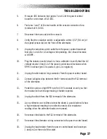
1.
Remove the neck covers (3300 CE only) and side covers.
2.
Unplug the battery from the power control board and locate pin 2 and
pin 3 in the end of the cable (see the wiring diagram).
3.
Use a voltmeter to verify that the voltage between pin 2
(Negative) and pin 3 (Positive) is a minimum of 6.0 VDC. Install the
battery charger for at least 24 hours if the voltage measured is below
6.0 VDC.
4.
Plug the battery cable back into the power control board,
Содержание STRATUS 3300 CE
Страница 1: ...Stratus Systems Owner s Manual...
Страница 66: ...Page 59 FIGURES Figure 11 Cover Fasteners...
Страница 67: ...Page 60 FIGURES Figure 12 Cover Fastener Locations 3300 CE...
Страница 68: ...Page 61 FIGURES Figure 13 Cover Fastener Location 3900 RC...
Страница 69: ...Page 62 Figure 14 Right Side View 3300 CE FIGURES...
Страница 70: ...Page 63 Figure 15 Left Side View 3300 CE FIGURES...
Страница 71: ...Page 64 FIGURES Figure 16 Right Side View 3900 RC...
Страница 72: ...Page 65 FIGURES Figure 17 Left Side View 3900 RC...
Страница 73: ...Page 66 FIGURES Figure 18 Seat Adjustment Pin Assembly 3300 CE...
Страница 74: ...Page 67 FIGURES Figure 19 Seat Assembly 3900 RC...
Страница 75: ...Page 68 FIGURES Figure 20 Drive Chain Tension...
Страница 76: ...Page 69 FIGURES Figure 21 Intermediate Shaft Assembly...
Страница 77: ...Page 70 FIGURES Figure 22 J Bolt Assembly...
Страница 78: ...Page 71 FIGURES Figure 23 Crank Assembly...
Страница 79: ...Page 72 FIGURES Figure 24 Alternator Flywheel Assembly...

