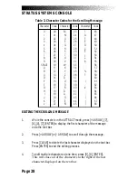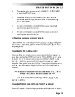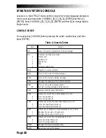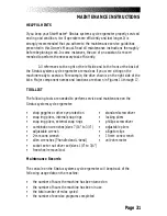
Page 42
Contact Heart Rate Test
The contact heart rate system is made up of the console and the contact heart
rate handles. You can test each component by performing the following steps:
1.
While the console is in the ATTRACT mode (noted by a simulated EKG
signal in the console display), or at the “SELECT A WORKOUT”
prompt, press [+INCREASE], [1], [0], [8], [ENTER].
2.
After approximately ten seconds a flashing
♥
should be displayed in
the console text bar. Your heart rate, in beats per minute, will show
next to the heart icon. If the heart icon does not show, or if your heart
rate is not displayed in the text bar, you have a problem with either
the console or the contact heart rate handles.
3.
If possible, replace or exchange your console with a console (from
the same type of machine) you know is working and retest the
machine.
4.
If possible, replace or exchange your contact heart rate handles with
handles (from the same type of machine) that you know is working
and retest the machine.
5.
If you do not have spare parts contact the Customer Service
Department at 800-331-3578.
Polar
®
Heart Rate Test
The Polar heart rate system is made up of the console, the heart rate receiver,
and the chest strap (available separately). You can test each component by
performing the following steps:
1.
You will need to put a chest strap on in order to test the Polar heart
rate. Before you put the chest strap on, wet the two contact patches.
Secure the chest strap as high under your pectoral muscles (chest) as
is comfortable. The chest strap should fit snugly, comfortably, and
allow normal breathing.
CONSOLE DIAGNOSTIC TESTS
Содержание STRATUS 3300 CE
Страница 1: ...Stratus Systems Owner s Manual...
Страница 66: ...Page 59 FIGURES Figure 11 Cover Fasteners...
Страница 67: ...Page 60 FIGURES Figure 12 Cover Fastener Locations 3300 CE...
Страница 68: ...Page 61 FIGURES Figure 13 Cover Fastener Location 3900 RC...
Страница 69: ...Page 62 Figure 14 Right Side View 3300 CE FIGURES...
Страница 70: ...Page 63 Figure 15 Left Side View 3300 CE FIGURES...
Страница 71: ...Page 64 FIGURES Figure 16 Right Side View 3900 RC...
Страница 72: ...Page 65 FIGURES Figure 17 Left Side View 3900 RC...
Страница 73: ...Page 66 FIGURES Figure 18 Seat Adjustment Pin Assembly 3300 CE...
Страница 74: ...Page 67 FIGURES Figure 19 Seat Assembly 3900 RC...
Страница 75: ...Page 68 FIGURES Figure 20 Drive Chain Tension...
Страница 76: ...Page 69 FIGURES Figure 21 Intermediate Shaft Assembly...
Страница 77: ...Page 70 FIGURES Figure 22 J Bolt Assembly...
Страница 78: ...Page 71 FIGURES Figure 23 Crank Assembly...
Страница 79: ...Page 72 FIGURES Figure 24 Alternator Flywheel Assembly...

