Page 52
PARTS REMOVAL AND REPLACEMENT
4.
Loosen and remove the bottom bracket jam nut located on the left
side of the crank (see Figure 23). This nut has reverse threads; loosen
it by turning it clockwise.
5.
Remove the round, metal crank shield from the left side of the crank.
6.
Remove the bearing clamps by loosening the allen bolts from the left
side clamp.
7.
The left bearing nut assembly can be removed from the crank with a
15-mm cone wrench. This nut has reverse threads; loosen and
remove it by turning it clockwise.
8.
Slide the crank out of the frame to the right.
9.
The right bearing nut assembly can be removed from the crank with a
32-mm cone wrench. The right bearing nut assembly also holds the
chain ring in place on the crank. If the chain ring is damaged, replace
it now.
10.
Inspect the bearings for smoothness of operation. Replace the
bearings if necessary.
11.
Ensure that the right bearing nut assembly is tight against the
chain ring before reinstalling the crank into the frame. The outside
edge of the bearing nut assembly should be flush with the bottom
bracket when the crank is installed.
12.
Install the left bearing nut assembly onto the crank and tighten it so
the outside edge of the bearing nut assembly is flush with the bottom
bracket (see Figure 23). Do not overtighten the nut; the crank should
spin freely.
13.
Install both bearing clamps and tighten the allen bolts. Do not
overtighten the allen bolts; the crank should spin freely.
Содержание STRATUS 3300 CE
Страница 1: ...Stratus Systems Owner s Manual...
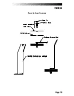
Страница 66: ...Page 59 FIGURES Figure 11 Cover Fasteners...
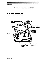
Страница 67: ...Page 60 FIGURES Figure 12 Cover Fastener Locations 3300 CE...
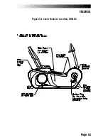
Страница 68: ...Page 61 FIGURES Figure 13 Cover Fastener Location 3900 RC...
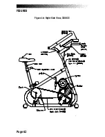
Страница 69: ...Page 62 Figure 14 Right Side View 3300 CE FIGURES...
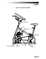
Страница 70: ...Page 63 Figure 15 Left Side View 3300 CE FIGURES...
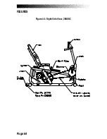
Страница 71: ...Page 64 FIGURES Figure 16 Right Side View 3900 RC...
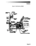
Страница 72: ...Page 65 FIGURES Figure 17 Left Side View 3900 RC...
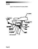
Страница 73: ...Page 66 FIGURES Figure 18 Seat Adjustment Pin Assembly 3300 CE...
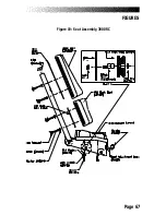
Страница 74: ...Page 67 FIGURES Figure 19 Seat Assembly 3900 RC...
Страница 75: ...Page 68 FIGURES Figure 20 Drive Chain Tension...
Страница 76: ...Page 69 FIGURES Figure 21 Intermediate Shaft Assembly...
Страница 77: ...Page 70 FIGURES Figure 22 J Bolt Assembly...
Страница 78: ...Page 71 FIGURES Figure 23 Crank Assembly...
Страница 79: ...Page 72 FIGURES Figure 24 Alternator Flywheel Assembly...

