Page 14
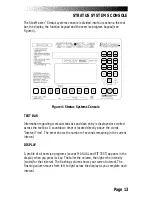
STRATUS SYSTEMS CONSOLE
Function keypad
The function keypad is located on the right side of the console. Nine of the keys
on the keypad have two pieces of information on them—a number and a
workout statistic. Before the exercise program begins, the numbers are used to
enter data in response to the console prompts. During or immediately after the
exercise program, the function keypad keys are used to recall workout statistics
which are then displayed on the text bar.
Time
. Displays the elapsed time of your workout, in minutes and
seconds.
Speed
. Displays the equivalent speed, in miles per hour (or
kilometers per hour if your console is set to metric units), you
would be traveling on a bicycle outdoors while riding at the same
relative intensity.
Distance
. Provides a cumulative total of the equivalent distance,
in miles (or kilometers if your console is set to metric units), you
would have traveled while riding a bicycle outdoors at the same
relative intensity.
Watts
. Displays the intensity in watts (746 watts = 1 horsepower). For
all programs, except the constant resistance ROAD RACE, the watts
remain constant in any given level as long as you pedal at least 50
RPM. During a workout, this key displays the power output at that
moment. Average power is shown during the workout summary.
Intensity Level
. Shows the current level between 1 (the easiest) and
20 (the hardest). Shows the number of lights in the MANUAL program
between 1 and 14.
METs
. Gives you the relative energy cost of exercise. MET stands for
multiples of the resting metabolic rate. While you are sitting quietly,
your body consumes oxygen at the rate of about 3.5 milliliters per
kilogram of body mass per minute. When you exercise, your body
needs more oxygen in order to function. For example, exercising at 10
METs requires ten times the resting rate of oxygen consumption, or
Содержание STRATUS 3300 CE
Страница 1: ...Stratus Systems Owner s Manual...
Страница 66: ...Page 59 FIGURES Figure 11 Cover Fasteners...
Страница 67: ...Page 60 FIGURES Figure 12 Cover Fastener Locations 3300 CE...
Страница 68: ...Page 61 FIGURES Figure 13 Cover Fastener Location 3900 RC...
Страница 69: ...Page 62 Figure 14 Right Side View 3300 CE FIGURES...
Страница 70: ...Page 63 Figure 15 Left Side View 3300 CE FIGURES...
Страница 71: ...Page 64 FIGURES Figure 16 Right Side View 3900 RC...
Страница 72: ...Page 65 FIGURES Figure 17 Left Side View 3900 RC...
Страница 73: ...Page 66 FIGURES Figure 18 Seat Adjustment Pin Assembly 3300 CE...
Страница 74: ...Page 67 FIGURES Figure 19 Seat Assembly 3900 RC...
Страница 75: ...Page 68 FIGURES Figure 20 Drive Chain Tension...
Страница 76: ...Page 69 FIGURES Figure 21 Intermediate Shaft Assembly...
Страница 77: ...Page 70 FIGURES Figure 22 J Bolt Assembly...
Страница 78: ...Page 71 FIGURES Figure 23 Crank Assembly...
Страница 79: ...Page 72 FIGURES Figure 24 Alternator Flywheel Assembly...


