Page 44
COVERS
3300 CE
The Stratus 3300 CE cycle ergometer is protected by four plastic covers: two
large side covers and two smaller neck covers. Refer to Figure 12 for the fastener
locations.
1.
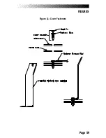
The neck covers are held in place with six reusable fasteners. Slide
either end of the fastener removal tool under the edge of the head pin
and pull the pin out about halfway (see Figure 11). The pin should not
be pulled out of the base. The neck covers must be removed before
the side covers are removed.
2.
Disconnect the battery charger from the connector located just inside
the bottom front corner of the side cover.
3.
Remove the four reusable fasteners from the side panels.
4.
Slide the square rubber grommet, on the seat tube, up the frame and
away from the covers.
5.
Move the crank to about the eleven o’clock position on the right side
to get the right side cover over the crank. Once the right cover is off
the frame, move the cranks to the one o’clock position on the left side
and remove the left cover.
6.
To reinstall the cover fasteners, insert the fastener base through the
cover and into the frame. When the base is in place, push the head
pin in all the way to secure the fastener (see Figure 11). Connect the
battery charger to the power connector once the side covers are
attached.
PARTS REMOVAL AND REPLACEMENT
Содержание STRATUS 3300 CE
Страница 1: ...Stratus Systems Owner s Manual...
Страница 66: ...Page 59 FIGURES Figure 11 Cover Fasteners...
Страница 67: ...Page 60 FIGURES Figure 12 Cover Fastener Locations 3300 CE...
Страница 68: ...Page 61 FIGURES Figure 13 Cover Fastener Location 3900 RC...
Страница 69: ...Page 62 Figure 14 Right Side View 3300 CE FIGURES...
Страница 70: ...Page 63 Figure 15 Left Side View 3300 CE FIGURES...
Страница 71: ...Page 64 FIGURES Figure 16 Right Side View 3900 RC...
Страница 72: ...Page 65 FIGURES Figure 17 Left Side View 3900 RC...
Страница 73: ...Page 66 FIGURES Figure 18 Seat Adjustment Pin Assembly 3300 CE...
Страница 74: ...Page 67 FIGURES Figure 19 Seat Assembly 3900 RC...
Страница 75: ...Page 68 FIGURES Figure 20 Drive Chain Tension...
Страница 76: ...Page 69 FIGURES Figure 21 Intermediate Shaft Assembly...
Страница 77: ...Page 70 FIGURES Figure 22 J Bolt Assembly...
Страница 78: ...Page 71 FIGURES Figure 23 Crank Assembly...
Страница 79: ...Page 72 FIGURES Figure 24 Alternator Flywheel Assembly...

