Page 17
STRATUS SYSTEMS CONSOLE
Fit Test
The Fit Test is a program developed by the YMCA to estimate your maximum
aerobic capacity based on your heart rate response to submaximal exercise. Start
the Fit Test by pressing [FIT TEST], [ENTER]. You will be prompted to enter your
weight, age, and gender after a short message is scrolled across the text bar.
The Fit Test is a series of three minute stages of increasing intensity.
Maintain a steady pedal rate of 50 - 70 RPM throughout the entire test. The first
stage is a warm-up at 50 watts. At the end of the three minute (180 seconds)
warm-up, you will need to enter your heart rate. If you are wearing a heart rate
transmitter, your heart rate is entered automatically.
NOTE: Keep pedaling until the end of the Fit Test. The results will be
invalid if you do not maintain a steady pedal rate for the entire test.
The console will prompt you to find your pulse; use the artery below
your thumb in your wrist or the artery in the side of your neck. Start counting the
beats when the console prompts you--the first beat you feel is zero and then one
and so on. Enter the number of beats you counted in ten seconds.
The intensity of the remaining stages is based on your heart rate
response to the warm-up. The intensity of each successive stage will increase
until you have entered two consecutive heart rates between 19 and 25 counts
(115 - 150 beats per minute). The test typically lasts from nine to 15 minutes.
At the end of the Fit Test, your results scroll across the text bar. Prior to
a three minute cool-down, your estimated maximum aerobic capacity is shown in
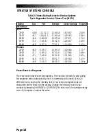
METs. Next, your results are compared to normative values for others of your age
and gender (see Table 2). Your results are stored in the console until the next
person starts an exercise program. Press [WORKOUT STATS] to review your
results.
Содержание STRATUS 3300 CE
Страница 1: ...Stratus Systems Owner s Manual...
Страница 66: ...Page 59 FIGURES Figure 11 Cover Fasteners...
Страница 67: ...Page 60 FIGURES Figure 12 Cover Fastener Locations 3300 CE...
Страница 68: ...Page 61 FIGURES Figure 13 Cover Fastener Location 3900 RC...
Страница 69: ...Page 62 Figure 14 Right Side View 3300 CE FIGURES...
Страница 70: ...Page 63 Figure 15 Left Side View 3300 CE FIGURES...
Страница 71: ...Page 64 FIGURES Figure 16 Right Side View 3900 RC...
Страница 72: ...Page 65 FIGURES Figure 17 Left Side View 3900 RC...
Страница 73: ...Page 66 FIGURES Figure 18 Seat Adjustment Pin Assembly 3300 CE...
Страница 74: ...Page 67 FIGURES Figure 19 Seat Assembly 3900 RC...
Страница 75: ...Page 68 FIGURES Figure 20 Drive Chain Tension...
Страница 76: ...Page 69 FIGURES Figure 21 Intermediate Shaft Assembly...
Страница 77: ...Page 70 FIGURES Figure 22 J Bolt Assembly...
Страница 78: ...Page 71 FIGURES Figure 23 Crank Assembly...
Страница 79: ...Page 72 FIGURES Figure 24 Alternator Flywheel Assembly...


