Engineering
18
221457 / 9475621310
2019-01-18·BA00·III·en·02
EN
EN
EN
EN
EN
EN
EN
EN
EN
EN
EN
EN
EN
EN
EN
EN
EN
EN
EN
EN
EN
EN
EN
EN
EN
Digital Output Module 4
-
Channel Version
for Zone 1
Series 9475/32-04-.2
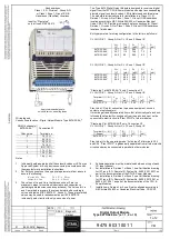
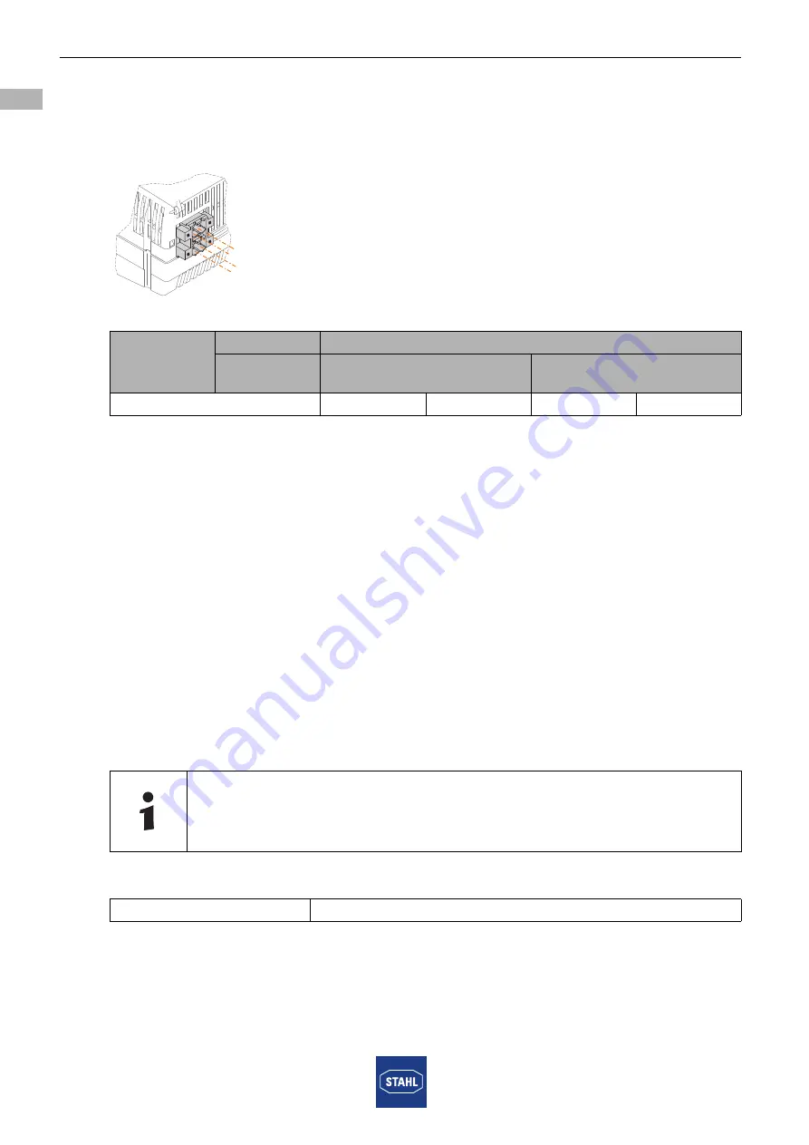
The modules also have a pluggable terminal X3 to connect to the "Plant STOP" electrical
circuit. The pluggable terminal X3 has 2 terminals. It can either be inserted into X3.1, X3.2
(contact) or X3.3, X3.4 (active input) at the module. Simultaneous insertion of terminals
into X3.1, X3.2 and X3.3, X3.4 is not possible.
15404E00
Notes on "Plant STOP"
• In the "Contact" operating mode, the "Plant STOP" function is compatible with the
9475/22 module. Here, the X3.2 terminal is connected to the X1(-) terminals of the
outputs via the earth.
However, this can only be done when connecting to the passive equipment such as
contacts or optocouplers!
"Plant STOP" must be galvanically separated from other intrinsically safe and
non-intrinsically safe circuits and from the earth and must not be connected to the
"Plant STOP" circuits of other modules.
• In the "Active input" operating mode at terminal X3.3 and X3.4, "Plant STOP" is
galvanically separated from all other electrical circuits and may be interconnected in
parallel with other modules. If "Plant STOP" is not used, terminals X3.1 and X3.2 must
be bridged (the jumper is included in delivery).
6.2
Line Fault Suppression
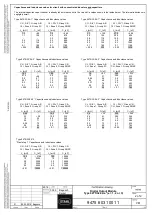
Optionally, non-used channels can be wired to resistors for suppressing line fault
indications.
Can be equipped as follows based on the signal type, e.g. channel 0:
Terminal
X3
Function
Terminal
operating mode
Contact
Active input
"Plant STOP"
1
2
3(+)
4(-)
The resistors are available as accessories.
Output
5K6 between clamping unit 1 and 2
X3
4
2
3
1
Содержание is1+ 9475/32-04 2 Series
Страница 53: ......


