Commissioning
22
221457 / 9475621310
2019-01-18·BA00·III·en·02
EN
EN
EN
EN
EN
EN
EN
EN
EN
EN
EN
EN
EN
EN
EN
EN
EN
EN
EN
EN
EN
EN
EN
EN
EN
Digital Output Module 4
-
Channel Version
for Zone 1
Series 9475/32-04-.2
8.3
Installation
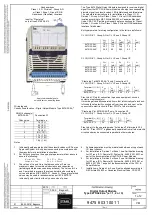
The cover flap features an insert disc which can be used to enter the assignment of the
field devices to the channels. IS Wizard can be used, for example, to label the insert disc.
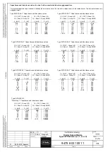
• Connect the field devices to the pluggable terminals X1 and X3 according to terminal
assignment (see the "Project engineering" section or insert disc on the inside of the
cover).
• Place the field wiring shields (if available) as close to the entry point on the earthing
rail as possible.
• Where necessary, snap the partition into place on the adjacent Ex i module.
• Plug the pluggable terminals X1 and X3 into the module and secure them against
loosening using screws (tightening torque 0.5 to 0.6 Nm).
• If necessary, connect the "System OFF" electrical circuit to the pluggable terminal X3.
9
Commissioning
Before commissioning, ensure the following:
• Installation of the device according to regulations.
• Correct connection of the cables.
• No damage at the device and connection cables.
• Tight seat of the screws at the terminals.
Correct tightening torque: 0.5 to 0.6 Nm.
Operation under difficult conditions, such as, in particular, on ships, requires
additional measures to be taken for correct installation, depending on the
place of use. Further information and instructions on this can be obtained
from your regional sales contact on request.
The module and the pluggable terminals X1 and X3 can be safely connected
or disconnected during operation in the hazardous area (hot swap).
Содержание is1+ 9475/32-04 2 Series
Страница 53: ......


