


221457 / 9475621310
2019-01-18·BA00·III·en·02
Engineering
17
EN
EN
EN
EN
EN
EN
EN
EN
EN
EN
EN
EN
EN
EN
EN
EN
EN
EN
EN
EN
EN
EN
EN
EN
EN
Digital Output Module 4
-
Channel Version
for Zone 1
Series 9475/32-04-.2
6
Engineering
The following conditions must be observed during project engineering:
• To ensure adherence with the intended use, only install the device on the
IS1 BusRail 9494.
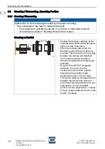
• Operation of the device is only permissible in three approved mounting positions:
See the "Mounting/dismounting on BusRail" section.
• Modules with intrinsically safe and non-intrinsically safe field circuits may be
operated simultaneously on one BusRail. In this case, a distance of 50 mm must be
maintained between the terminals with intrinsically safe field circuits and those with
non-intrinsically safe field circuits (e.g. partition 220101 or empty space).
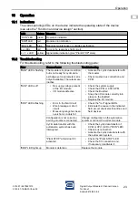
6.1
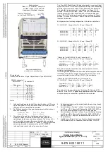
Terminal Assignment of the pluggable Terminals X1 and X3
For the module, a plug-in terminal X1 (screw terminal 162702 or spring clamp
terminal 162695) for connecting field devices is available as an accessory
(not included in the scope of delivery of the module).
The X1 plug-in terminal has 16 clamping units for connecting the field cables.
15324E00
All earth connections (channel 0 to 3) are connected.
NOTICE
An ambient temperature that is too high may cause failure of the devices installed
in the cabinet.
Non-compliance can result in material damage.
• Install and adjust the cabinet in such a way that it is always operated within
the permissible temperature range.
Terminal
X1
Function
Channel
0
1
2
3
Signal input (+)
1
5
9
13
Earth
2
6
10
14
X1
1 2
3
4
5
6
7
8
9 10 11 12 13 14 15 16
Содержание is1+ 9475/32-04 2 Series
Страница 53: ......


