


9475 6 031 001 1
1 of 2
2016
03.03. Bagusch
Kaiser
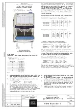
Digital Output Module
Type 9475/32-04-e* (e = 1, 2 or 3)
01 09.03.2018 Bagusch
Nonhazardous
Class I, II, III, Division 1, Group A-G
or Class I, Zone 1, Group IIC/IIB
Hazardous (Classified) Locations
Input for “Plant-stop”
only at type 9475/32-04-*2
Approved intrinsically safe
solenoid valves, indicating lamps
Wiring legend
Connection allocation
– Digital Output Module Type 9475/32-04-**
DOM (4 channels)
9475/32-04-**
Channel no.
Connection X1
Terminal no.
0
1(+), 2(-)
-
3(+), 4(-)
1
5(+), 6(-)
-
7(+), 8(-)
2
9(+), 10(-)
-
11(+), 12(-)
3
13(+), 14(-)
-
15(+), 16(-)
Notes:
1.
Intrinsically safe apparatus shall be solenoid valves or LEDs or an
Approved System or Entity device connected in accordance with
the manufacturer´s installation instructions.
2.
For Entity concept use the appropriate parameters from above to
ensure the following:
V
OC
or V
t
V
max
C
a
C
i
+ C
leads
I
SC
or I
t
I
max
L
a
L
i
+ L
leads
3.
The values of La and Ca in the tables on sheet 2 are the
maximum values for combined inductance and capacitance
(including cable inductance and capacitance). The values for La
and Ca marked in grey are the values determined according to
curves and tables of IEC 60079-11, Annex A. These grey marked
values may be used for assessment as per IEC 60079-14,
intrinsically safe circuits with only one source of power.
The Type 9475 Digital Output Module is designed to receive a digital
signal from the IS1 CPU & Power Module and output a corresponding
discrete signal to solenoid valves, LED initiators and audible alarms.
The module is intrinsically safe for installation in a Class I, II, III,
Division 1, Group A-G or Class I, Zone 1, Group IIC/IIB hazardous
location according to NEC Article 504/505 or Canadian Electrical
Code, CSA C22; Providing intrinsically safe connections for Class I,
Division 1, Groups A-G or Class I, Zone 0, Group IIC/IIB hazardous
locations listed below.
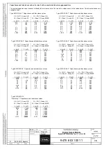
Entity parameters for wiring configuration to the left are as follows:
CL I,II,III, DIV 1, Group A-G or CL I, Zone 0, Group IIC
V
OC
[V]
I
SC
[mA]
P
O
[mW]
Ci
[nF]
Li
[mH]
9475/32-04-1*
9475/32-04-2*
9475/32-04-3*
19.7
25.7
26.0
142
110
90
698
708
585
11
7.2
5.2
0
0
0
CL I,II,III, DIV 1, Group A-G or CL I, Zone 1, Group IIC
V
OC
[V]
I
SC
[mA]
P
O
[mW]
Ci
[nF]
Li
[mH]
9475/32-04-1*
9475/32-04-2*
9475/32-04-3*
19.7
25.7
26.0
53.8
49.5
50.4
617
648
508
11
7.2
5.2
0
0
0
“Plant-stop I” at 9475/32-04-*2 only, Connection X3
CL I,II,III, DIV 1, Group A-G or CL I, Zone 0, Group IIC
Terminal 1(+), 2(-)
(3-4 open)
V
OC
[V]
I
SC
[mA]
P
O
[mW]
Ci
[µF]
L
i
[mH]
9475/32-0*-*2
5.1
0.44
0.50
5.2
0
Plant-stop I: Only for connection to passive equipment, such as
contacts or optocouplers!
It must be galvanically separated from other intrinsically safe and non-
intrinsically safe electric circuits and from the earth and must not be
connected to electric circuits "Plant STOP" of other modules.
“Plant-stop II” at 9475/32-04-*2 only, Connection X3
CL I,II,III, DIV 1, Group A-G or CL I, Zone 0, Group IIC
Terminal 3(+), 4(-)
(1-2 open)
V
i
[V]
Ri
[Ω]
Ci
[nF]
L
i
[mH]
9475/32-0*-*2
30
4940
0
0
Plant-stop II: In the operating mode "Active input" at terminals X3.3
and X3.4, "Plant STOP" is galvanically separated from all other electric
circuits and may be connected in parallel to other modules.
4.
Suitable separation must be maintained between wiring of each
I.S. input channel.
5.
For Installation in Division 1 or Zone 1 see Certification drawing
for IS1 resp. IS1+ Remote I/O System No. 9400 6 031 003 1 as
part of the documentation of the CPU & Power Modules.
6.
For Installation in Division 2 or Zone 2 see Certification drawing
for IS1 resp. IS1+ Remote I/O System No. 9400 6 031 004 1 or
9400 6 031 006 1 as part of the documentation of the CPU &
Power Modules.
7.
Installation in Division 2 or Zone 2 is also allowed according to
NEC Article 504/505 or Canadian Electrical Code, CSA C22.
Содержание is1+ 9475/32-04 2 Series
Страница 53: ......


